Yanhua ACDP Mini Wiring Diagram:
Suitable for EEPROM 24 25 93 95 Series
Used for in circuit (ICP)and on board(OBP)programming
Features:
No need to remove chip
No need soldering
No need to cut the line
No need to lift the pin
Wiring:
How to use with OBP + ICP adapter
Good to know where is:
Patch (SOP) soldering area
DIP chip area
20 pin extension area
8 pin extension area
CAN terminal resistance setting area

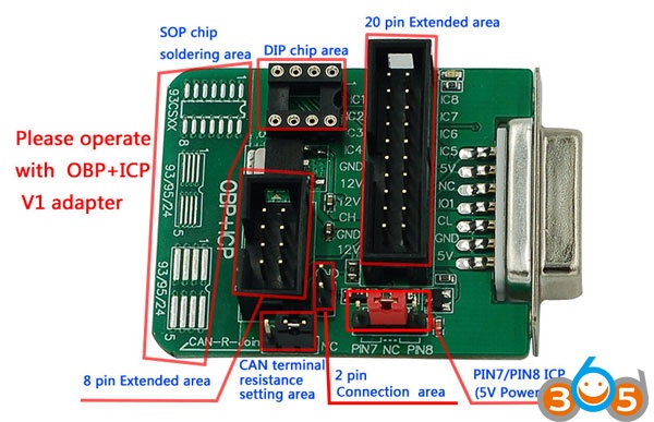
How to use with OBP + ICP V1 adapter
Good to know where is:
Patch (SOP) soldering area
DIP chip area
20 pin extension area
8 pin extension area
CAN terminal resistance setting area
2 pin connection area
Pin 7 / pin 8 ICP (5V power setting area)
How to identify the first pin of SOP8 chip:
Method 1:
The pin corresponding the round point is the first pin
Method 2:
The leftmost pin on the side of chip slope is the first pin

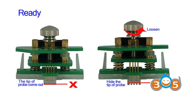
Ready for key programming:
Hide the tip of probe
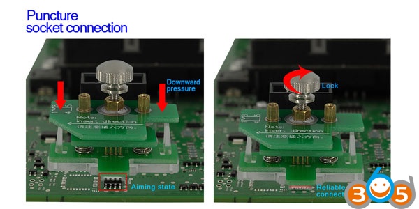
Puncture
Socket connection:
Check the lock and reliable connection state
How to connect the adapter to ACDP mini:

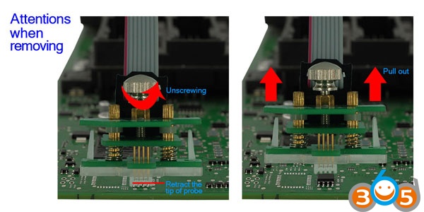
Attention please when removing:
Retract the tip of probe
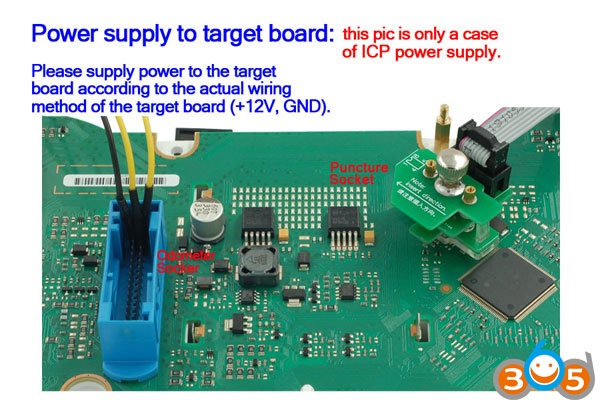
Power supply to the target board:
Pls supply the power to the target board according to the actual wiring method of the target board (+12V, GND)
Note that the pic here is only an example of ICP power supply
OBP connection diagram:
Mode 1:
Insert the DIP8 chip in the 8-pin DIP socket directly
Mode 2:
Solder the SOP8 chip on the corresponding solder pad with the soldering iron
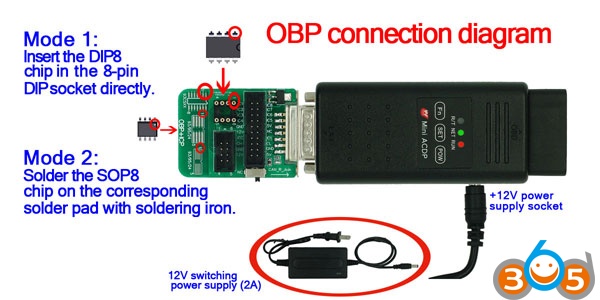
You should have 12V switching power supply (2A)
Yanhua Mini acdp Tech Support: http://www.obdii365.com/