Finally works! I can confirm that the wiTech Micrpod2 clone off obdii365.com does work with the DRB3 emulator for a 2003 Dodge Ram Cummins. I am able to access all the control module ECM Cluster Airbag ABS FCM… It was not easy. I had to add some welding on the electronic board of the Micropod. I follow this guide.
The guide was shared by a user from jeepforum.com.
Why need to fix the micrpod2 clone?
I bought a Micropod 2 clone and it works, but only can communicate with PCM (2002 Jeep WJ Overland 4.7L HO). When I try the other modules I get an error. There are still a lot of useful function just in the PCM. I have tried various combinations of witech and DRB emulator versions. Tried on XP and win7. No matter what still can only read PCM.
A friend of mine tried the same exact Micropod 2 clone with the DRB3 emulator program, but the result is the same as me, only access the engine, no transmission and no other modules.
Experiments:
I confirmed that the Micropod 2 clone uses SCI to communicate with the PCM and not PCI. I did this by removing my Pin 2 wire from the DLC connector then attaching Micropod and was able to read the PCM. Again still no other modules.
I measured pin 2 of the device and saw a steady ~4.8V on an O-scope. Checking other devices that use PCI to comm this should be low ~0V except when communicating. I’m not even 100% sure the Micropod uses PCI communication but considering the other modules only have PCI wires going to them, seems to be the issue. I have read tho that sometimes there is a gateway between the buses which would likely be in the PCM.
I am considering tinkering with my device to see if I can get PCI communication working.
Result:
I was able to figure out the issue and get my Micropod 2 clone reading all modules! But I ruined my device in the process of figuring it out. I found the issue right after I accidentally touched some pins together causing the device to constantly reset. So I wasn’t able to try the fix out unless I bought another device and applied the fix I found. I was highly confident that the issue I found, once resolved would allow for communication with the other modules. So I bought another device, tested it first to make sure it worked and acted the same as the other one. Sure enough, could access only PCM. I applied my fix and Voila! was able to access all modules.
So the issue with the device is that PCI communication does not work. SCI still works so it can communicate with the PCM only. I found a bad trace on the board causing one of the IC to not have a ground. This left the output floating at around 4.8V . Once I fixed the trace issue and the IC had it’s ground, pin 2 for PCI comm stayed at 0, unless there was communication happening.
Procedure:
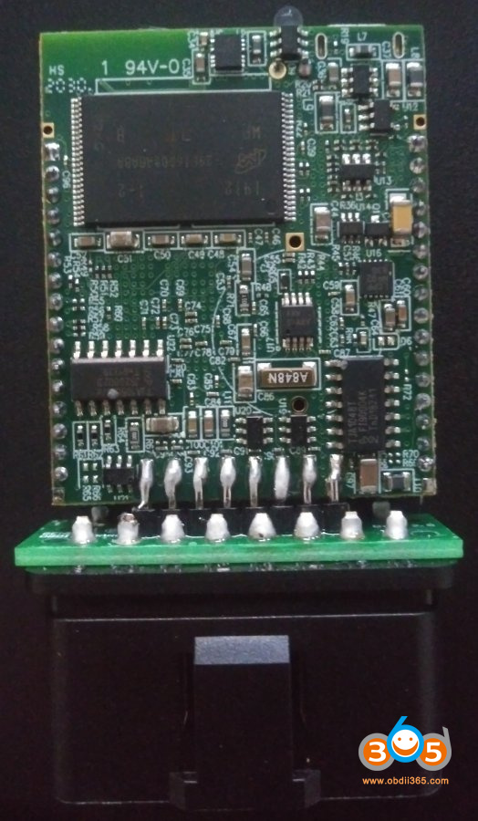
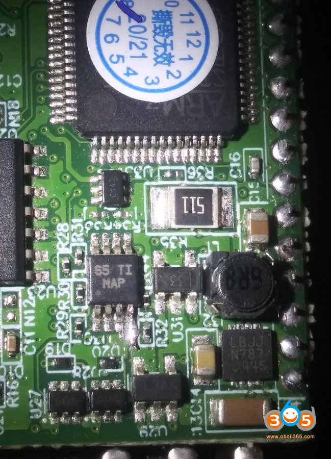
It is a little tricky, definitely needs a very fine point solder iron. I also used a solder station with varying temp so I didn’t overheat the trace. Also very important to use a ground strap, this is part of the reason I fried my first one. But mostly using T-pins to probe the board while it was powered on  Like I mentioned before, the issue is the IC with marking 65 TI MAP doesn’t have it’s ground. The trace between the via and the pin is bad.
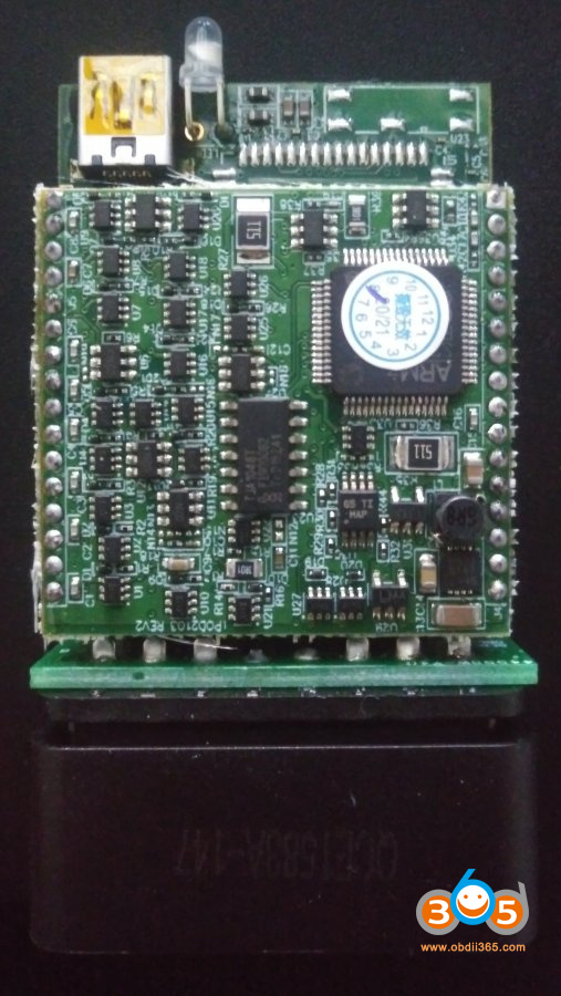
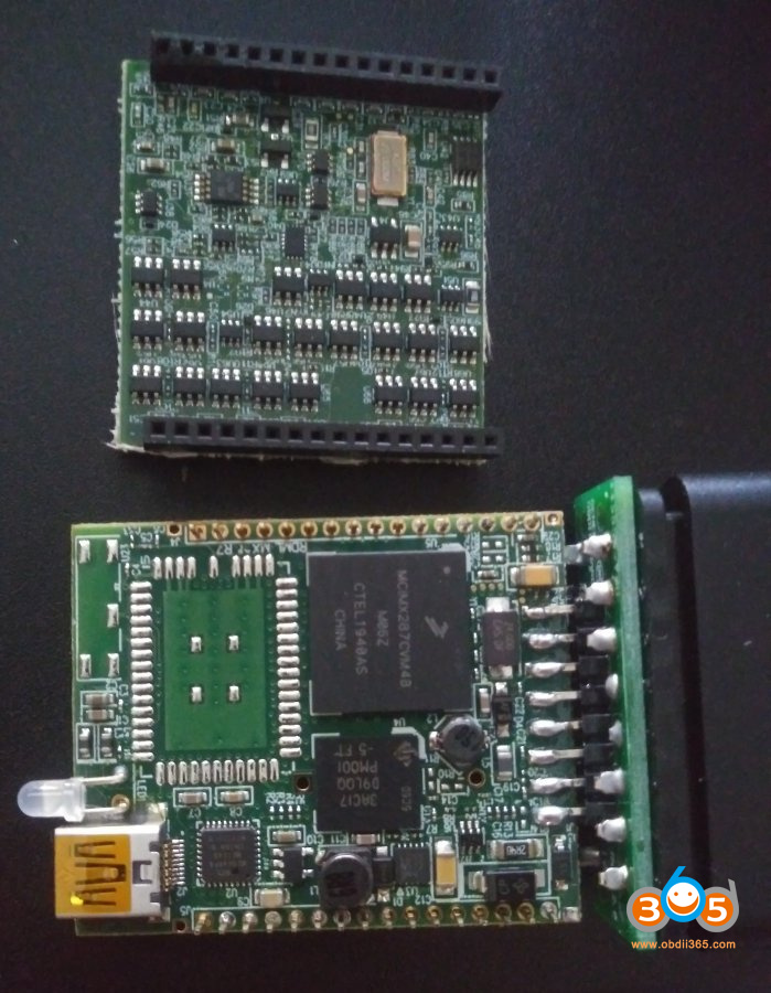
What I did was use an Exacto knife to scrape the coating off the top of the via, and very carefully make a solder bridge from the pin to the via. I considered using a very fine piece of wire as a trace but if you have ever tried it, you would prob know why I decided not to. I made sure the IC pin had ground but wasn’t accidentally shorted to the pin next to it. Also, make sure it’s not shorted to R32 which is very close by. I figured this out partly because there is another IC with marking 65 TI MAP on the inside of the board and it had ground at the same pin. To be clear, the IC with ground issue is on same board side as the ARM chip as seen in photos. You DO NOT need to separate the boards to fix it. And that’s it, when this IC has it’s ground the output won’t be floating high and the comm signal can be read by ARM chip.
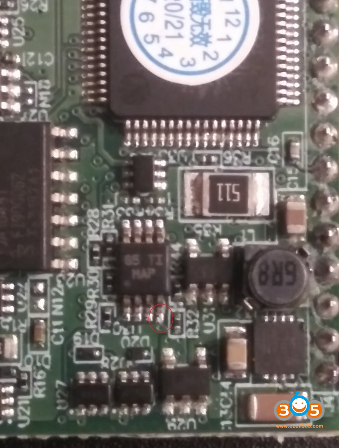
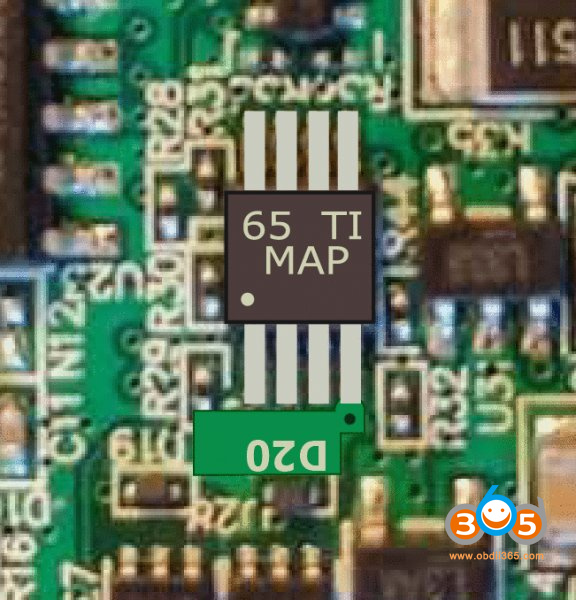
The pin of the 65 TI was supposed to touch the ground on the PCB but it doesn’t. I’ve made this image to compare the wrong (original) and the correct cutout:
I just played around with the micropod ii for a bit, accessing all the modules and seeing what functions are available. Some of the features I found useful were:
ABS bleed brakes – has you push the brake pedal and release a few times. then sounds like it vents out. so cool! I bled my brakes manually awhile back after rebuilding all the calipers but was never able to do this function.
Memory Seat Module – had a re-calibrate seat option and it drove all the motors to end of travel. I recently took my seat tracks apart so definitely needed to do this!
MIC (instrument panel) – drove all gauges to different values to make sure they are calibrated correctly. actually looked like my fuel and voltage were off a little.
and of course it can program key fobs (PDM) and keys (SKIM). It was really cool to see DTC stored in modules that you would never see otherwise. You can actuate almost every motor, relay, solenoid.
Related reading:
How to install DBR III for Micropod II on Windows 7?