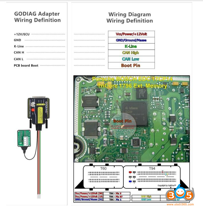
Where to get the wiring diagram to the Godiag ECU Boot GPT adapter?
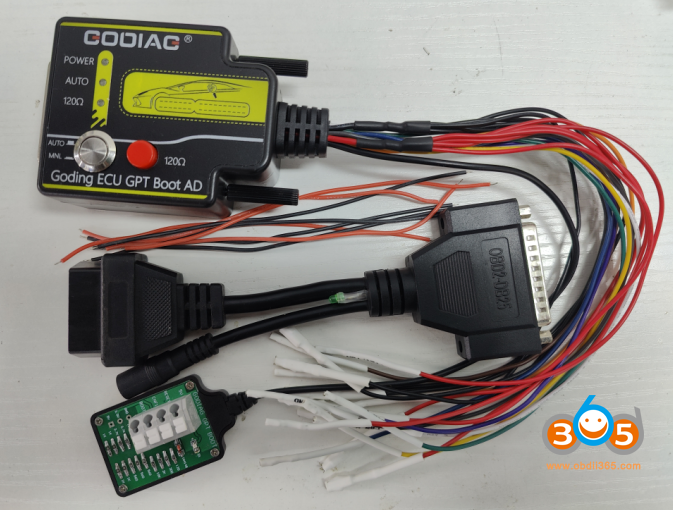
The Godiag ECU adapter can be used with J2534 devices (openport 2.0, SM2 pro etc) to read ECU on bench, GPT, Boot and via OBD on bench mode.
Obdii365.com here shows you how to find wiring diagram to the ECU adapter.
GODIAG ECU GPT Boot AD Programming Adapter can be used for ECU PINOUTs of different manufacturers and brands according to the wiring definition.
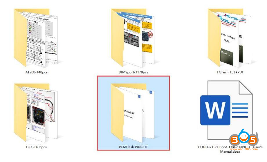
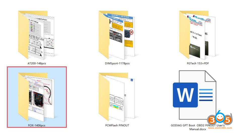
1. For the wiring diagram using PCMFLASH PINOUT, please refer to https://pcmflash.ru/downloads/english.html
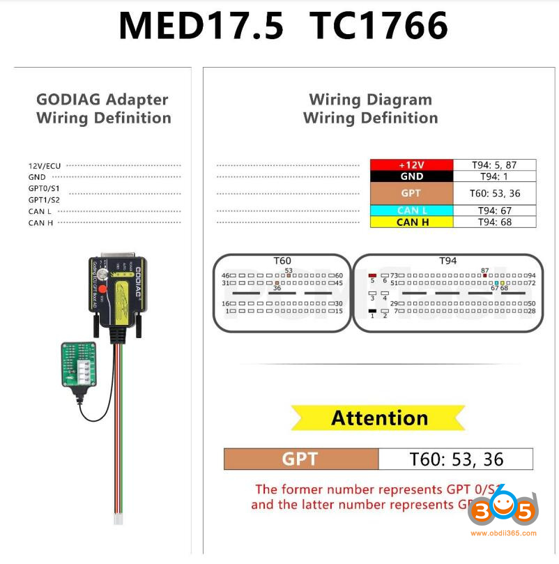
For example:
MED17.5 TC1766 bench pinout
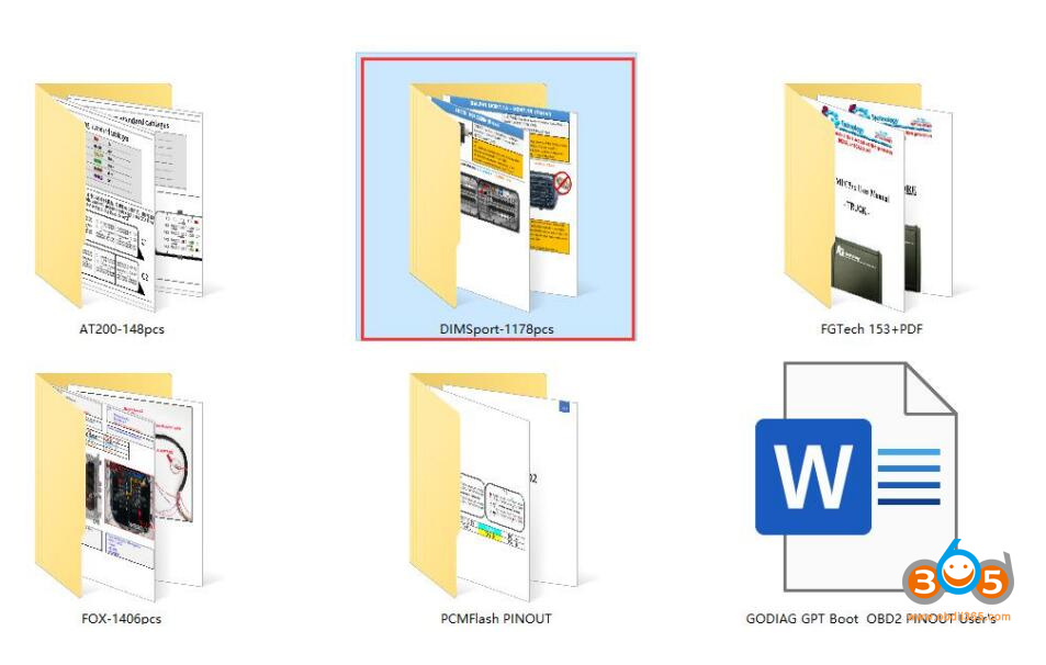
2. Using DIMSport KESS V2 KTAG products PINOUT connection diagram
For example:
3. For the PINOUT connection diagram of EVC products, please refer to
https://www.evc.de/en/product/bsl/ecu.asp
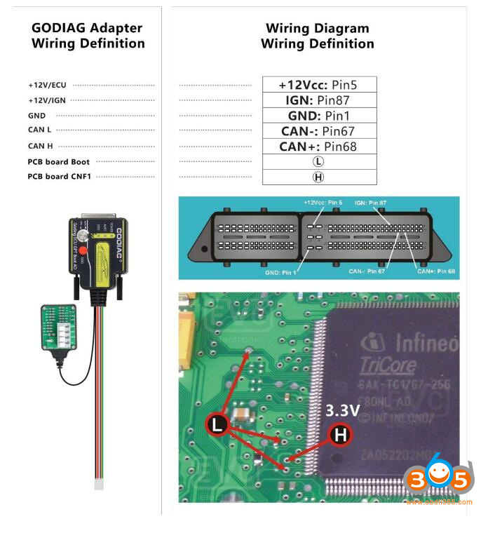
The L connection point is connected to the Boot connection port on the godiag ECU adapter, and the H point is connected to CNF1
4. For the PINOUT connection diagram of kt-prog or Foxflash FGtech products, please refer tohttps://wiring.fg-technology.uk/index.php?m=Home&c=wiring&a=index
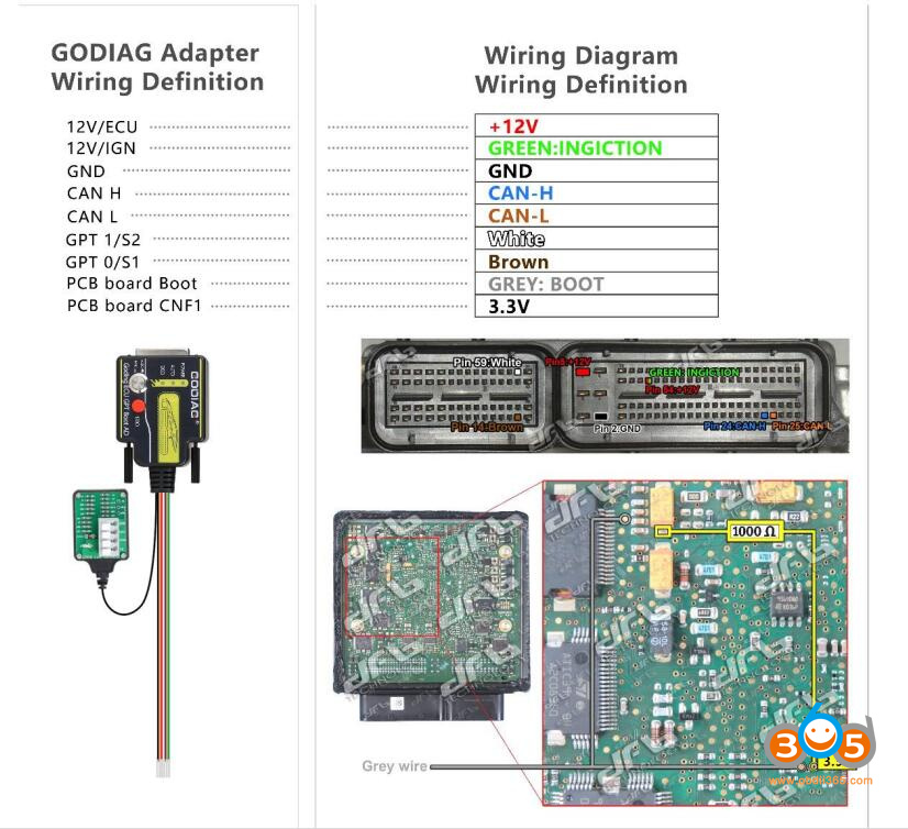
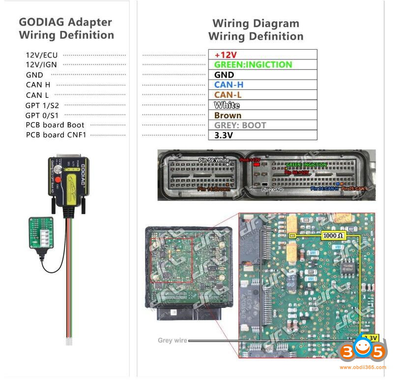
The Gray line connection point in the picture is Boot. The CNF1 or 3.3V in the picture is connected to the 1KΩ resistor point, or the resistor is connected as shown in the picture. The brown wiring in the picture is connected to GPT0, and the white wiring in the picture is connected to GPT1.
5. For the PINOUT connection diagram of obdtuning products, please refer to
https://wiki.obdtuning.de/index.php/Hauptseite
OBD2 Bench, GPT Bench, Boot
For example
FYI: For those who buy the godiag gpt/boot adapter, free to contact us to get these wiring PDFs.
Skype:OBDII365.com
Email:Sales@obdii365.com
WHATSAPP:+86 18150118226


