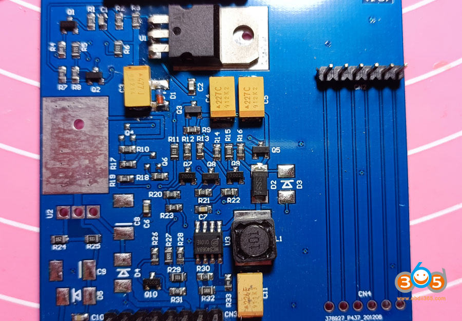
iProg+ clone PORT errors are because you probably didn’t change pull-up resistor on the mainboard and 10V & 12V errors are because you probably didn’t change the resistor in ADC voltage divider on the mainboard and from what you see in the pictures you didn’t replace the MC3406 current sense resistors with 0.22 Ohm. You can just put 3×1 Ohm in parallel instead of 12x||1R00.
PORT Error example:
— External power test —
FAULT – EXTERNAL POWER IS NOT CONNECTED.
— Pin test —
PORTD.1 (pin 6): OK.
PORTE.0 (pin 7): OK.
PORTE.1 (pin 8): OK.
PORTE.2 (pin 9): OK.
PORTE.3 (pin 10): OK.
PORTE.4 (pin 23): OK.
PORTE.5 (pin 24): OK.
PORTE.6 (pin 25): OK.
PORTE.7 (pin 27): OK.
PORTD.6 (pin 5): OK.
PORTA.0 (pin 20): FAULT
PORTA.1 (pin 21): FAULT
PORTA.2 (pin 22): FAULT
PORTB.0 (pin 19): FAULT.
PORTB.3 (pin 18): FAULT.
PORTA.5 (pin 2): FAULT.
PORTA.6 (pin 17): FAULT
PORTA.7 (Pin 1): FAULT
PORTB.4 (Pin 16): OK
PORTB.6 (Pin 4): FAULT
PORTB.5 (pin 3): FAULT
First replace two resistors as in the picture main_board_anmated. The resistor marked with the green dot has to be 4k7 and the other one marked with the blue dot has to be 51k.
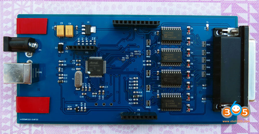
main_board_anmated
Measure the resistance with mulimeter to check if everything is OK. Between green points it shoud be 4k7 and between blue points it should be 61k.
since your 10V and 12V results are exactly the same, that means the current sense resistor Rs (two parallel resistors on the board as I said in the last post) which is used for programming maximum current at the output of MC34063AG DC-DC converter is wrong – the current limit is too low to get more than 6.5 V. You can use this online calculator to calculete Rs:
http://www.nomad.ee/micros/mc34063a/index.shtml
Or just replace the resistors in the powerboard as showed in this picture:
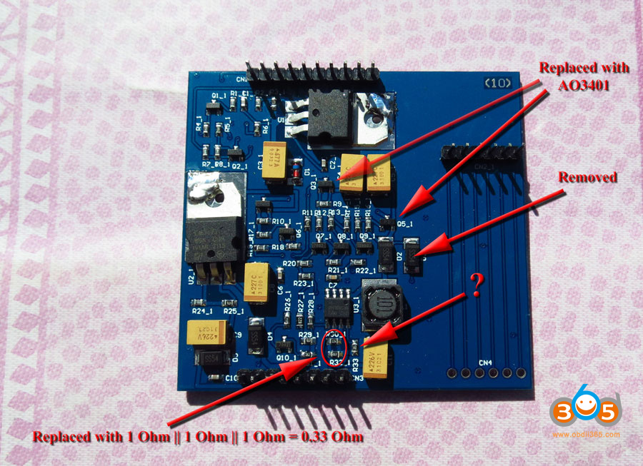
If your board has some other DC-DC converter then look at the datasheet and calculate the value of Rs. If you have MC34063AG Rs should be 0.22 Ohm but it can work with 0.33 Ohm too. If you don’t have 0.22 Ohm 0603 resistor just solder three 1 Ohm resistors of any size in parallel to get 0.33 Ohm.
Maybe you will not have to replace the transistors but better if you do.
Then test MBUS/UART/BDM adapter and if you get 5.5V instead of 7.5V replace the Zener diode to get the correct voltage.
And the most important – don’t power iProg directly from laptop or PC USB port, use a good powered USB hub which has at least 2A power supply and which has backfeeding protection. You can find the list of all USB hubs with backfeeding protection somewhere on Raspberry Pi Wikipedia.
Don’t forget to plug the power supply for the USB hub when you are programming microcontrollers – if you forget to plug it then 12V will jump over 14V, 10V will jump over 12V, 5V will jump over 6V and 3.3V will jump over 4V.
When you plug only the USB hub into the PC or into the laptop then iProg is powered from weak USB power supply from the computer and the current goes through very long cable between the computer and the USB hub and then current goes through another USB cable between USB hub and iProg. Computer port current limit is only 500 mA and the voltage is usually about 4.9V but as soon as iProg draws current the voltage at the iProg input drops and then there is a jump in the voltages inside iProg – you can check it with test scripts or with the oscilloscope. 10V and 12V are derived from step-up controller which overcompensates voltage drops and voltages for adapters are derived from the same voltages.
On the other hand, powered USB hub voltage is usually 5.1V and is stable even when the device draws more than 1A.
Backfeeding is not powering the devices you connect to the USB hub, it is when you connect the USB hub to the external power supply and if USB hub is not powering just the devices you connect but is trying to power your computer too which is not good.
read also