GM Tech 2 TIS2000 user manual:
What is TIS2000?
What is TIS used for?
Where to get TIS2000 cracked?
How to install TIS2000?
How to use TIS2000?
How to do SPS with TIS2000?
Definition:
What is TIS2000?
TIS (Time in Service) 2000 is the Vauxhall Dealer’s official diagnostic software for all of the Vauxhall range. It’s very unlikely that anyone would have this legitimately unless they were a dealer as it’s supplied and supported by Vauxhall and isn’t cheap, therefore if people have this or offer to sell it then it will more than likely be a counterfeit copy which is why we don’t allow discussion of it on the forum (it’s in the rules )
Functionality:
Tis2000 is only used for SPS programming, and the Tech II is put into pass through mode when using such.
On export vets, you have to use SPS programming for programming in fobs, since the key in the cylinder does not work on them.
Operating system:
As for Tis2000, need to run under XP,.
So the short version, build a VM shell in XP with something like VM work station on your win 10 machine, load the three discs to the VM shell, install the crack, then build the driver.
64bit or 32bit system?
64-bit versions of Windows contain backwards compatibility with 32-bit applications, but not with 16-bit applications. And 32-bit versions of Windows are backwards compatible with 16-bit applications. The problem with installing TIS2000 on newer machines is that, while the TIS2000 program itself is 32-bit, the installer and drivers are 16-bit. Therefore, you are able to install TIS2000 natively on ANY 32-bit Windows system. This will just work, without having to run anything in compatibility mode.
However, if you have a 32-bit copy of Windows 8 installed (I don’t wanna know why you do), running 16-bit applications are disabled by default. You can enable it by going to Control Panel and clicking on 16-bit Application Support then clicking Enable.
Windows xp or Windows 7?
For those of you with genuine copies of Windows 7 Professional, Enterprise, or Ultimate with a multi-core processor (who doesn’t run Win7 on a multi-core these days); these versions of Windows 7 allow you to use Windows Virtual PC, which lets you virtually run Windows XP Pro without a disc or OS installation. You need to install Windows XP Mode and Windows Virtual PC in order to use it. Before you can download these updates, M$ makes you run a little .exe that checks if your OS install is legitimate. Anyway, after you get that all installed and XP Mode is booted, you can copy the OP’s cracked TIS2000.zip over to the WinXP Desktop and follow the README.txt inside to install it.
Laptop requirement:
If your laptop does not have a RS232 port, then will need to buy the needed usb cable to connect the Tech II to the laptop, and make sure to install the needed USB driver into the the XP shell as well.
Drivers are listed about half way down on the page.
https://www.automationdirect.com/adc/shopping/catalog/communications/serial/industrial_usb/usb-rs232
Software source:
As for the cracked Tis2000 (all three disc’s and dongle crack), pretty easy to find for free on the web with a search to download it for free.
TIS2000 GM:
TIS2000 Saab:
Tis2000 installation:
Steps in detail to install TIS2000:
http://blog.obdii365.com/2017/12/12/install-tis2000-globaltis-for-gm-tech2/
TIS2000 XP Win 7 Win 8 32/64 bit install:
http://blog.obdii365.com/2018/03/14/install-tis2000-on-windows-xp-7-8-64bit-or-32bit/
Tis2000 how to use:
–Insert the TIS 2000 CD into the computer, Tis2000 helps to get the latest calibration for the PCM
–Connect your Tech2 scan tool with laptop with a RS232 pass-thru interface
–Start the GM recalibration software program on your PC and welcome the vehicle information (year, make, model, etc.) program
— Connect the Tech 2 scan tool into the vehicle’s diagnostic socket
–Turn the deice ignition switch on and wait for the start screen
–Confirm the vehicle VIN number
— Choose the operating system, engine, fuel system, speedometer or transmission.
— Select “normal reprogramming” or “VCI” (special modifications).
— Choose the update bulletin/recalibration number from the menu.
–The system now starts transferring data. It will last about 3 minutes. You will notice that the PC screen will display a blue progress bar as the software is uploading to the vehicle. (The GM setup will not allow the same calibration to be reinstalled over itself. Only an updated calibration can be loaded into the vehicle computer.)
–When the system completes loading software, the windows will pops out “PROGRAMMING COMPLETE” message.
–Turn off the Tech2 ignition and disconnect it from the vehicle.
Note that GM Tech2 with TIS2000 works better with vehicles before 2007
Tis2000 programming procedure: (SPS)
The GM Service Programming System (SPS) is a personal computer (PC) application used to reprogram vehicle electronic control modules (ECMs). The SPS application programs General Motors programmable control modules by using the Tech 2 Flash scan tool or the Next Generation scan tool as a “pass-thru” device to communicate program data to the vehicle control module. All programming steps are activated and finalized through the PC
Service Programming System software CDs
GM Service Programming System kit contains two compact discs (CD):
- An Application CD which loads the SPS application
- A Data CD which loads SPS data
System Requirements
SPS application install
Step 1: Determine if TCP/IP protocol is installed
– If you have a network card installed then you only need to verify that TCP/IP protocol has been configured.
– If your PC is already set up with TCP/IP protocol, go to “Install the SPS Software”
Step 2: Install the SPS Application CD software
To install the SPS software, follow these steps:
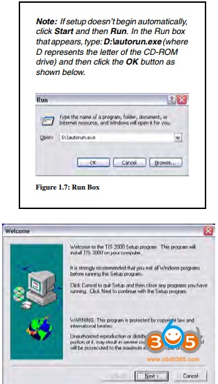
1 Insert the Application CD into the PC’s CD drive.
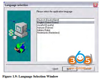
The TIS 2000 Installation Welcome window appears automatically
(Figure 1.8).
Note: If the TIS2000 software was previous installed and removed from the PC, a message may appear asking to reuse old settings. If so, click the NO button to NOT reuse old settings.
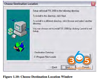
2 Click the Next button to continue. This displays the Language Selection window.
3 Select a language for the application and then click the Next button. This displays the Choose Destination Location window.
4 Click the Next button. This displays the Choose Serial Port window (Figure 1.11).
Note: Clicking the Next button on the Destination Location window places the SPS application in the destination directory C:\Program Files\cosids. You can optionally click the Browse button to select a different destination directory for the files.
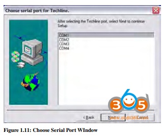
5 Select the serial port to use for the scan tool connection. This must be an open COM port where no external devices are connected. Then click the Next button. This displays the TIS2000 Installation Mode window.
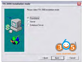
6 Select Standalone and then click the Next button. This displays the Set DEALERSHIP window.
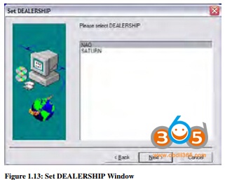
7 Select NAO (North American Operations) and then click the Next button. This configures settings, starts the
Decurity Device Installation module, and displays the TIS2000 Security Device Add / Remove window.
Note: This installation of TIS2000 supports reflash of Saturn vehicles. Other dealership installations are not supported.
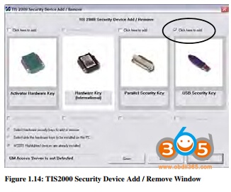
Note: The Security Device Installation module configures the USB security key, which is a component of the SPS Kit. The installation of the USB security key requires strict attention or TIS2000 will not perform as expected.
8 Click the checkbox above USB Security Key to place a checkmark in the box (Figure 1.14). Then click the Continue button. This displays an Information window (Figure 1.15).
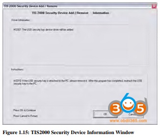
9 Follow the instructions on the Information window and then click the OK button. This displays a Hardware Installation message box.
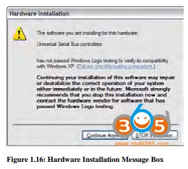
10 Click the Continue Anyway button. This displays the Program Completed window.
11 Install the purple USB security key as instructed on the window and then click the OK button.
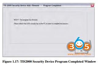
Note: Make sure the security key installs securely into the PC’s USB port. After installing the software, do not remove the security key from the USB port; it must remain in the port for the TIS2000 SPS application to work. 12 This begins the TIS2000 software installation and displays a progress indicator message (Figure 1.18).
Wait for the installation to complete and for the completion message to appear (Figure 1.19).
13 Click the OK button.
14 Remove the Application CD from the PC’s CD drive.
15 Go to Update the SPS Data
Step 3: Update the data with the SPS Data CD
Note: During the update, the TIS2000 software skips the initial language, dealership, etc. steps and uses current TIS2000 settings. TIS2000 also skips over SecDevIns (Security Device Installer) and uses the current TIS2000 settings.
1 Insert the Data CD into the PC’s CD drive and wait approximately 20 seconds for the TIS2000 Update message to appear.
Note: On Windows XP systems, a browser window may open displaying the contents of the CD. If so, close the window and double-click the TIS2000 icon on the Window’s desktop. Because TIS2000 looks for new updates each time you start the application, the Update message appears.
2 Click the OK button to continue. This begins the update and displays a progress indicator message. When the update completes, a completion message appears
3 Click the OK button. The application is ready to use.
4 Begin using the SPS application by double-clicking the TIS 2000 icon located on the Window’s desktop.
Tech 2 Flash Setup
What You Will Need for Tech 2 Flash Setup:
1 The GM SPS application installed onto your PC
(with the USB security key). Also see “System Requirements” on page 1
2 32 MB PCMCIA card recommended (May, 2005). Call OTC Technical Services at 800-533-6127 to determine
the current minimum requirements.
3 SPS Kit Components:
- RS-232 DB9 Serial Port Adapter (P/N 3000111)
- RS-232 Communications Cable (P/N 3000110)
- USB Security Key (already installed during software installation)
- RS-232 Loop-back Adapter (P/N 3000112)
- User’s Guide (P/N 526933)
4 T2F Kit Components (from Tech 2 Flash Kit):
- Tech 2 Flash Scan Tool
- Cigarette Lighter Power Cable (P/N 3000096) or Battery Power Cable (P/N 3000097)
- SAE 16/19 Pin Adapter (if the vehicle is OBD II compliant)
- NAO 12/19 Pin Adapter (if the vehicle is not OBD II compliant)
- (Optional) AC to DC Power Supply (P/N 3000113)
- DLC Cable (P/N 3000095)
- DLC Loop-back Adapter (P/N 3000110)
Step 1: Verify the Tech 2 Flash and DLC Cable (Power On Self Test – POST)
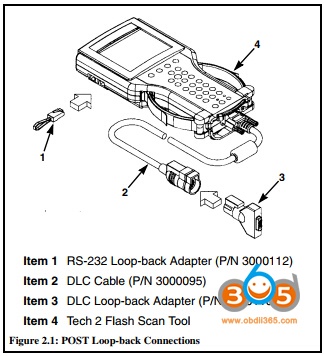
1 Make the loop-back connections as follows:
a Plug the RS-232 loop-back adapter (item 1) into the
Tech 2 Flash RS-232 port. See Figure 2.1.
b Connect the DLC cable (item 2) to the Tech 2 Flash VCI connector.
c Connect the DLC loop-back adapter (item 3) to the
DLC cable.
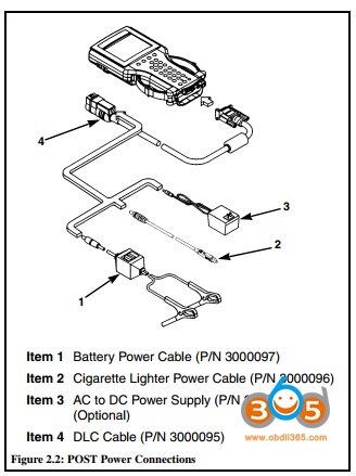
2 To make the power connection, connect one of the following to the power jack on the DLC cable
(see Figure 2.2. – Item 4):
- battery power cable (item 1), or
- cigarette lighter power cable (item 2), or
- the optional AC to DC power supply
3 Supply power to the Tech 2 Flash.
4 Perform the Power On Self Test (POST) as detailed in the
Tech 2 Flash User’s Guide.
5 The POST automatically verifies the hardware and detects any Tech 2 Flash malfunctions. Do one of the
following:
- If any errors are detected, refer to the POST
Troubleshooting Chart located in the Tech 2 Flash
User’s Guide.
- If no errors are detected, go to the next step.
6 Disconnect the RS-232 loop-back adapter, the power
supply, and the DLC loop-back adapter.
7 Go to the steps
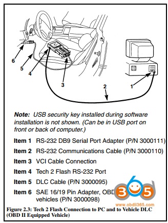
Step 2: Connect the Tech 2 Flash Scan Tool to the PC and to the Vehicle DLC
1 Connect the RS-232 DB9 serial port adapter (Item 1) to the open COM port on your PC that you selected when you installed the SPS application.
2 Connect the RS-232 communications cable (Item 2) to the DB9 serial port adapter (Item 1) and to the Tech 2 RS-232 port (Item 4).
3 If the vehicle is OBD II equipped (Figure 2.3), connect the SAE 16/19 pin adapter (Item 6) to the DLC cable (Item 5).
(If the vehicle is non-OBD II equipped, skip this step.)
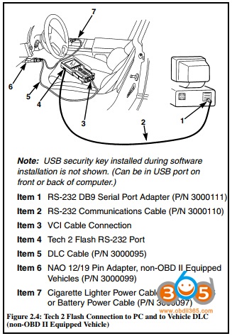
4 If the vehicle is non-OBD II equipped (Figure 2.4), make the following connections. (If the vehicle is OBD II equipped, skip this step.)
a Connect the NAO 12/19 pin adapter (Item 6) to the DLC cable (Item 5).
b Connect a power supply (Item 7) to the DLC cable (Item 5).
c Connect the power supply to the appropriate power source (cigarette lighter, battery, or outlet).
5 Connect the DLC cable (Item 5) to the Tech 2 VCI cable connection (Item 3).
Service Programming Cautions
CAUTION: There are a number of programming preparations that must be followed exactly or permanent damage to a reprogrammable control module could result:
- Battery voltage – The battery must be between 12.6 and 14 volts. The battery must be completely charged before programming. Important: Do not program while charging the battery. Connecting a second battery in parallel to the vehicle battery helps prevent drawing the battery charge low enough to cause a fatal error to the vehicle ECM while programming.
- Ignition key on, engine not running – One of the PC message screens requests that the ignition key be turned on, engine not running. Important: Do not turn the key to any other position until the programming is complete. Once programming is complete, turn the ignition key off, wait about 30 seconds, and then disconnect the tools. This allows time for the vehicle computer to power down properly.
- Power interruption – Important: During programming, do not interrupt power or DLC connections in any way. This could cause permanent damage to the reprogrammable control module. Before programming, check all connectors and cords for wear, and check all connections to be sure they are secure. All cords must be properly routed and secure to prevent any entanglement with feet or hands.
- Tampering – A new control module is not preprogrammed. The memory of an in-use reprogrammable control module contains the vehicle identification number (VIN) as well as calibration data. In the course of reprogramming an in-use control module, the VIN and the calibration date are replaced. The VIN entered into the scan tool must match the VIN on the vehicle’s VIN plate. It is important that the correct VIN be installed in the control module for future service and in the event of a recall campaign that requires reprogramming the module. Other information entered into the program must also be correct. Programming improper calibration data could adversely affect vehicle exhaust emissions resulting in violation of emission control laws and regulations.
- Self-starting computer applications – ALL personal computer applications must be turned off before you use the SPS application. A screen saver, virus detection application, network connections, or any other applications that can activate without user prompting must also be turned off to prevent any disruption in communication. Any disruption during the reprogramming function can cause a programming failure and damage the vehicle computer.
- Current drain – Headlights and fans may be activated during the reprogramming steps. This can cause enough current drain to the battery to bring the battery voltage below an acceptable level for programming, or low enough to damage the vehicle computer. Set the parking brake to disable “automatic on” headlights. Remove the fuses for high current body electronic circuits, but do not remove the fuse for the vehicle computer circuit.
- Doors may lock – During programming, leave a window open to enable access into the vehicle.
Tech 2 TIS2000 Tech Support: http://www.obdii365.com/