What is electrical wiring diagram:
An electrical wiring diagram (also known as a circuit diagram or electronic schematic) is a pictorial representation of an electrical circuit. It shows the different components of the circuit as simplified and standard pictograms, and the power and signal connections (buses) between the devices. Arrangement of the components and interconnections on the diagram does not usually correspond to their physical locations in the finished device.
vehicle wiring diagrams includes wiring diagrams for cars and wiring diagrams for trucks.
CAR wiring diagram software:
Mercedes-Benz WIS/EPC:
http://www.obdii365.com/wholesale/2017-09-mb-star-sd-c4-hdd.html
W-I-S net 2017.04: Workshop Information System
EPC.net 2017.04: Electronic Parts Catalog

Provide the whole view of the wiring diagram in a car,component location diagram and maintenance method. What you do is to enter the chassis number, and then you will get the manufacture data, engine configuration and the car model -all in detail.
Porsche PET 7.3 electronic spare parts catalogue:
http://www.obdii365.com/wholesale/porsche-pet-73.html
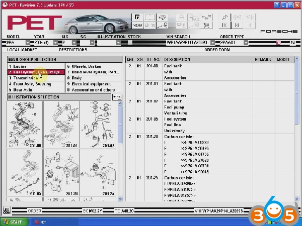
The spare parts catalog Porsche allows to enter VIN number of the machine and carries out a filtration, using it, but thus number of a body is not taken into account, that is the program Porsche will define on VIN model and modelling year (using first 11 symbols VIN), the rest should be chosen independently. It means, that the program Porsche easy digests VIN numbers with thought up last figures that can lead to to mistakes in identification of units.
BMW ETK 3.1.30 BMW Electronic Parts Catalog:
http://www.obdii365.com/wholesale/bmw-electronic-parts-catalog-etk.html
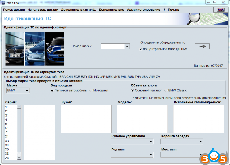
BMW ETK contains the full range of parts offered for sale by BMW Group and is intended to facilitate the retrieval of necessary spare parts (car parts and motorcycle), supplies and accessories. Added to the price list in the BMW ETK Local with ETK Admin.
To do this at your disposal a variety of search functions, such as searching by name, by part number, etc. In addition, the system offers detailed information on specific details, as well as the ability to create so-called parts list of found parts.
Audi VW Skoda Seat Electronic Service Information ELSAWIN 5.2:

ELSAWIN 5.2 for Audi-VW-SKODA-SEAT has full information on repair basically on new automobiles 1986-2011, electric schemes 1992-2009, incl. detailed description of technology of repair, electric schemes, bodyworks, the catalogue of spare parts for guarantee replacement, esp. the information of new and old machines
Land Rover electronic calatogue:
http://www.obdii365.com/wholesale/land-rover-microcat-electronic-parts-selling-system.html
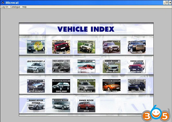
Microcat Electronic Parts Selling System for Land Rover, the newest version is 2013.07, supports multi-vehicles. It includes the information for all kinds of land rover series and for different years.
wiring diagrams for TRUCKs:
Clark ForkLift (PartProPlus) Electronic Spare Parts Catalogs:
http://www.obdii365.com/wholesale/clark-forklift-partproplus-electronic-spare-parts-catalogs.html

The interface of the spare parts program Clark Fork Lift very simple and convenient, is search on model, serial numbers, the list of applicability of a detail as the program contains service bulletins.
John Deere Parts Catalogue:
http://www.obdii365.com/wholesale/john-deere-power-systems-cd.html

John Deere Component Technical Manuals, John Deere Operation and Maintenance Manuals, Service Pricing Guides, John Deere Parts Catalog, John Deere PowerTech.
Hitachi Parts Catalogue:
http://www.obdii365.com/wholesale/hitachi-parts-catalogue-2013.html

Hitachi parts catalogue 2013 is for heavy construction machines, parts catalog for Hitachi equipment, equipment types covered by Hitachi HOP 2013.
MAN heavy duty truck WIS/EPC:
http://www.obdii365.com/wholesale/man-mantis-2015-catalogue.html

(Mantis) 2015 Workshop Info System EPC Electronic Parts Catalogue V5.9.1.85
The parts catalog MAN MANTIS contains the complete information about spare parts for trucks, buses and various chassis of special assignment, and also about engines MAN. This catalog includes a lot of pictures, illustrations with detailed description of equipment components.
Caterpillar ET 2017A V1.0 Electronic Technician:
http://www.obdii365.com/wholesale/caterpillar-et2017A-electronic-technician-diagnostic-software.html
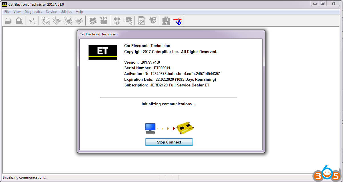
Cat ET (Caterpillar ET) 2017A is an updated version of the dealer level program for the diagnosis of all equipment Caterpillar.
This program works with the dealer diagnostic scanner Caterpillar Communication Adapter, as well as other adapters for diagnostics including scanner Nexiq, the program provides the full information when troubleshooting. When you purchase a program Cat ET (Caterpillar ET) 2017A once you get detailed and clear instructions on how to activate it.
Good for you:
Universal automotive wiring diagrams:
VVDI Prog: http://www.obdii365.com/wholesale/vvdi-prog-programmer.html
Ktag: http://www.obdii365.com/
Kess v2: http://www.obdii365.com/
Free car wiring diagrams download free:
https://cardiagn.com/wiring/
How to read automotive wiring diagrams:
Wiring diagrams and road maps have much in common. Road maps illustrate how to get from point “A” to point “B.” However, instead of connecting interstates, highways and roads, a wiring diagram shows major electrical systems, sub-systems and individual circuits, all inter-connected. Another feature they have in common are layers of detail. For example, if you look at a road map of California, you won’t be able to locate a street address in Los Angeles. You might find a city or town, but you won’t find a specific address. In order to find the exact location of a particular residence or building, you would need a detailed street map or go online and use Google Maps or the GPS feature on a smartphone.
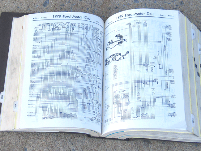 |
| While this wiring diagram for a 1979 Ford Mustang is dated, the skills required for using it to diagnose an electrical problem are no different than when viewing an online diagram from a late-model automobile. Unfortunately, there are no instructions as to how to actually read, and/or interpret most wiring diagrams whether in print, on a DVD or online. |
Wiring diagrams and road maps have much in common. Road maps illustrate how to get from point “A” to point “B.” However, instead of connecting interstates, highways and roads, a wiring diagram shows major electrical systems, sub-systems and individual circuits, all inter-connected. Another feature they have in common are layers of detail. For example, if you look at a road map of California, you won’t be able to locate a street address in Los Angeles. You might find a city or town, but you won’t find a specific address. In order to find the exact location of a particular residence or building, you would need a detailed street map or go online and use Google Maps or the GPS feature on a smartphone.
The same is true (to a lesser extent) of wiring diagrams. Vehicles made before the 1970s usually had their wiring diagrams contained on one, or two pages in a service manual. By the 1980s the complexity of automotive, on-board electronics changed and most vehicle manuals had multiple pages of wiring diagrams to show all of a vehicle’s electrical system. In the 1990s printed service manuals started to disappear and now manuals, and wiring diagrams are found on digital media or online. There is one aspect of wiring diagrams that has unfortunately remained constant. They lack directions regarding how to actually read them. Similar to a map, wiring diagrams will have a legend where symbols and naming conventions are spelled out but no “how-to” instructions.
While online automotive service manuals are written with the “professional” technician in mind, every technician had to learn to read and interpret wiring diagrams at some point in their career. The design and layout of wiring diagrams do not accommodate intermediate, or entry-level technicians by starting with easy-to-understand circuits that become progressively more difficult to read and understand. This article will take a different approach and begin with simple circuits and wiring diagrams, then move on to diagrams with more complexity. This step-by-step process not only makes learning to read a wiring diagram less painful, it promotes a greater understanding of how electrical circuits operate. Becoming more proficient at anything, including reading wiring diagrams, involves practice and there are some challenging questions included for that purpose as well.
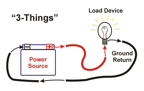 |
| A light bulb powered by a battery illustrates the 3-Things that all 12-volt electrical circuits must have to operate — Power, a Load Device and Ground Return. While this may seem obvious, locating the 3-Things, plus whatever controls the circuit, on a wiring diagram that spans many pages is not a simple process. |
3 Things
The simplified wiring diagram of the battery, light bulb and wires is easy to understand. However, if this same circuit was more complicated and included several relays, multiple power sources and a computer controlling the entire circuit, the resulting wiring diagram would be far more challenging to read. A quick review of basic electrical circuits will make understanding how they are depicted in a wiring diagram easier to understand. Every electrical circuit on an automobile has to have 3 things to operate: 1) a power source, 2) load device, and 3) a ground return. The charging system and battery function as power sources and are extended throughout the entire car by way of numerous wires. Load devices are simply anything that does electrical work and can include lighting, starter motor, on-board computers, relays, power windows, keyless entry and many other components. The ground return completes the electrical path from the battery positive terminal, to the load device and back to the battery negative terminal. If any of the 3 things are missing, the circuit won’t operate and wiring diagrams provides a “map” to assist in determining which of the three is not present.
In addition to the 3 things, load devices must be controlled. Some load devices are switched on or off by controlling their power source, while others are controlled by switching the ground returns on or off. The most common scenario is using a vehicle’s electronic control unit, or ECU, to ground relays that in turn control load devices. The process of figuring out how a load device is controlled and its power and ground sources can be determined by using a wiring diagram. To learn a logical process for reading complex wiring diagrams we’ll start out with a simple fog light circuit.
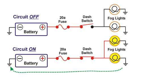 |
| Figure 1 is not typical of wiring diagrams found in a service manual. The fog lights circuit is shown in both ON and OFF states and uses colored lines to illustrate the presence of power. The green, dashed line shows how electricity travels back to the battery’s negative terminal after providing power for the fog lights. |
Figure 1 is a simple wiring diagram showing a fog lighting circuit. The circuit consists of a battery, 20-amp fuse (used to protect the circuit), a switch (located on a dash panel), and two fog lights. Ground returns are shown by the ground symbol of a vertical line with three horizontal lines. Not all wiring diagrams show ground wires and it is assumed the ground symbols indicate wires that are connected to the negative battery terminal. This diagram is unusual in that the presence of 12 volts is illustrated with the circuit in both ON and OFF states. Red lines indicate the presence of 12 volts and black lines represent the ground side of the circuit that connects to the battery’s negative terminal. In the circuit OFF part of the diagram, 12 volts is shown to be present from the battery, through the fuse and to the open dash switch. The lower part of the diagram shows the dash switch closed, connecting the battery to the lights and turning them on. It also illustrates one aspect of Kirschoff’s Law that the load device(s) will use all the power (12 volts) in the circuit as the voltage at the negative battery terminal, and on the ground side of the fog lights, is close to 0.0 volts. Unfortunately, actual wiring diagrams do not provide any of these advantages and late model automobile diagrams may not isolate circuits to this extent — more likely they will be part of the overall lighting system. Color, if used at all in a wiring diagram, is for the purpose of identifying individual wire colors, not to indicate power and ground sides of a circuit. In addition, wiring diagrams always default to show a load device in its OFF state and technicians have to imagine the presents of power throughout the circuit with the load turned on and operating.
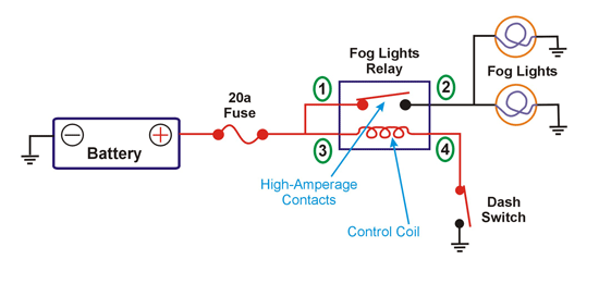 |
| Figure 2 shows that a relay has been added to the fog lights circuit. Instead of using a switch as in Figure 1, a relay now controls the high amperage current that the lights require in order to operate. The dash panel switch is used to energize the relay’s control coil that connects power from the battery to the fog lights through the high-amperage contacts inside the relay. |
 |
| Relays like this one are used in many 12-volt automobile circuits. They are typically controlled by a computer and provide power to various load devices. These relays can have 4 or 5 terminals. The fifth terminal indicates that the relay is a changeover type, with the fifth terminal normally closed (provides power) when the relay is off. Four-terminal relays only provide power when they are switched on. |
There is an inherent problem with the design of the fog lights circuit as shown in Figure 1. These particular fog lights require high amperage (8 amps each, or 16 amps total) from the battery to operate and this high electrical load has to travel through all the wires and dash panel switch to reach the lights. The wires, and especially the switch, would have to be heavy-duty to handle the high current. A simple solution is the addition of a 12-volt relay as shown in Figure 2. The relay takes the place of the heavy-duty switch and provides the high-amperage connection between the fog lights and the battery. The dash panel switch is still a part of the overall circuit, but now it only has to switch the low-amperage relay control coil (0.3 amps) instead of the high-amperage fog lights. The dash panel switch, and the wires connecting it to the circuit, can be smaller because the relay is connecting the battery to the lights and not the switch.
The control coil inside the relay is an electro magnet, and when terminal 4 of the relay is connected to ground by the dash panel switch, the coil is energized and pulls down the high-amperage contacts within the relay connecting terminals 1 and 2. This diagram does shows the circuit in the OFF position and is more typical of a real wiring diagram as the technician has to visualize where power is present in the circuit when the lights are on.
While Figure 2 illustrates the basic layout of how a relay is used to operate a high-amperage circuit, it has relevance to modern electronics used in today’s automobiles. Many automotive circuits are controlled by the vehicle’s PCM (power control module) that cannot directly control high current loads. The use of multiple relays solve this problem as the PCM only has to switch the low-amperage relays on and off.
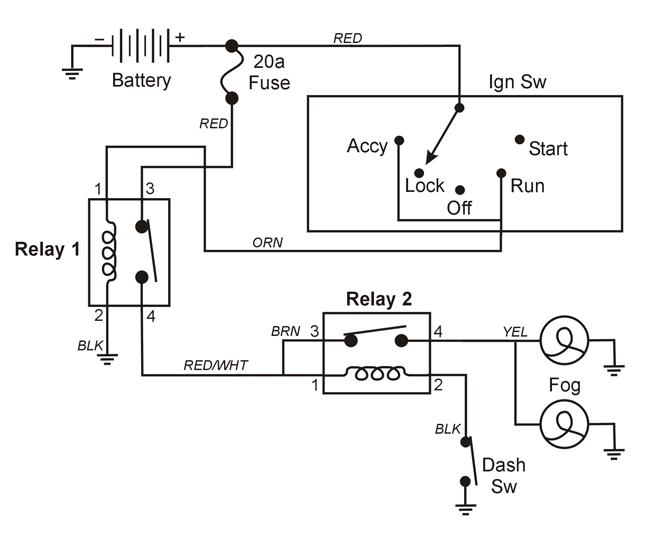 |
| Figure 3 shows a more sophisticated fog lights circuit that has the addition of a second relay. The design of this circuit prevents the fog lights from being turned on if the ignition switch is not in the run or accessory positions regardless of the dash panel switch being left on. |
The wiring diagram depicted in Figure 3 shows how the addition of a second relay to the fog lights circuit improving its functionality. Relay #1 provides power to relay #2, the same relay depicted in the previous diagram. Relay #1 is controlled by the ignition switch and only allows the fog lights to operate when the ignition switch is in the accessory or run positions. If the ignition key is in the lock or off positions, or removed from the ignition switch completely, no power is available at Relay #2. This prevents the fog lights from being left on inadvertently, even if the dash panel switch is left on. This diagram is more typical of wiring diagrams found in a service manual. Wires are identified by their color, but there is no color indicating where power is present; the circuit is shown in its OFF state and the relay terminals are identified by number.
The most effective way to learn how to read and use wiring diagrams is to practice. With that in mind, the following three practice questions will test your knowledge and ability read and interpret wiring diagrams. We’ll go through the first two questions together and leave the third one for you to answer.
Automotive electrical wiring diagrams Questions
Question 1. This question refer to Figure 3. With the ignition switch in the “Acc” position, and the dash panel switch off, what terminal numbers on relays #1 and #2 will have 12-volts? Figure number three is typical of wiring diagrams found in a service manual. Relays and switches are shown in their “open” position and color is not used to indicate where power or grounds are present. When reading any wiring diagram, start where a known source of power (12-volts) is located, usually at the battery positive terminal. Relay #1, terminal 3, is directly connected to the battery via the 20-amp fuse. Terminal 1 goes to the ignition switch and in the “Accy” position will also have 12-volts (RED wire to the ignition switch and the ORN wire between the switch and relay). Terminal 2 is a constant ground for the relay’s control coil. The relay is ON and terminals 3 is connected to 4 via the high-amperage contacts.
Relay #2 terminals with 12-volts are: 1 (RED/WHT) and 3 (BRN) that receive power from terminal 4 on relay #1. Terminals 1 and 2 are connected via the relay’s low amperage control coil, therefore terminal 2 has power because the dash switch is open. If the dash switch was closed, terminal 2 would show 0 volts because it is connected to ground and the relay would be “On.” Terminal 4 has no power because the relay is “Off.”
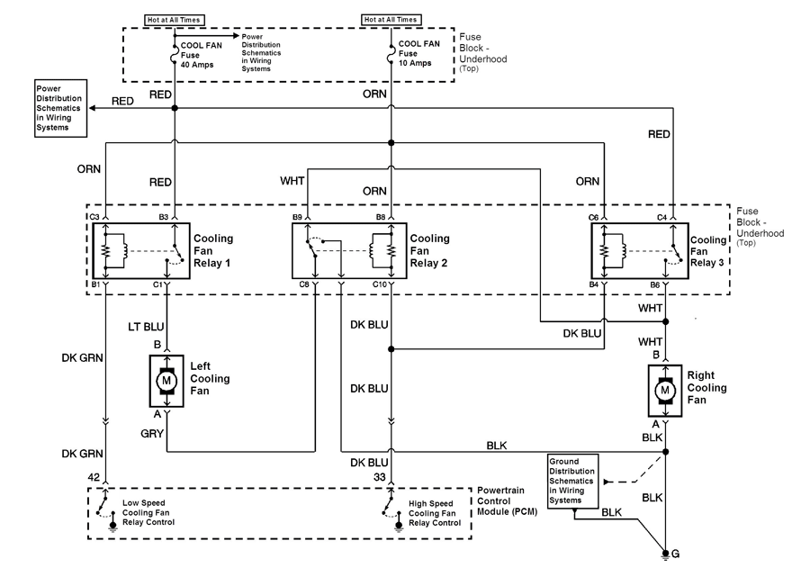 |
| This wiring diagram shows the cooling fan circuit for a late model automobile. The circuit has three relays, controlled by the vehicle’s power control module (PCM), that operate the fans in low or high-speed modes. Wires are identified by wire color. Cooling fan relay terminals are also identified with a letter and number. |
Question 2. Trace the path that provides power and ground to each cooling fan in the high-speed mode.
Question 2 uses a wiring diagram that is more complex than the one used for the first question. Figure 4 is a typical automotive wiring diagram that shows a radiator cooling fan circuit. Two fuses (40 and 10 amps) power the circuit and are directly connected to the vehicle’s battery (Hot at All Times). There are three relays that connect power to the cooling fans and control low and high speeds. The relays are controlled by the vehicle’s power control module, or PCM. The diagram also contains notes regarding labeling of components, their physical location and information on what other wiring diagrams are part of the overall circuit. The relay control coils look a little different that those in Figure 3. A resister is shown (zagged line) and is used to prevent voltage spikes from reaching the PCM when the relay is operated. Otherwise the relays work the same as those in Figure 3.
NOTE: This circuit operates on 12-volts. However, when the engine is running the operating voltage is 14-volts, or charging voltage provided by the alternator.
The three cooling fan relays determine the power and ground paths to the cooling fans. To run both cooling fans in the high-speed mode, the PCM grounds both terminals 42 and 33 (low and high-speed cooling fan relay controls). With PCM terminal number 33 grounded, the DK BLU wire becomes the ground for the cooling fan relay #3’s control coil at terminal B4. This turns the relay on because terminal C6 has power all the time from the 10 am fuse. The RED wire at terminal C4 of the relay is connected to the 40 amp cooling fan fuse and with the relay on connects to terminal B6 within the relay. The WHT wire from the relay (terminal B6) is connected to the right cooling fan and provides power. The right cooling fan has a constant ground on the BLK wire. With 14 volts (engine running) on the WHT wire and a ground on the BLK wire the right cooling fan runs at high-speed.
The left cooling fan receives power from the 40a fuse on the RED wire at cooling fan relay #1 (terminal B3). The PCM low speed cooling fan relay control (42) is grounded by the PCM providing a ground at terminal B1 (DK GRN) wire at cooling fan relay #1. On the same relay, terminal C3 gets power from the 10a fuse on the ORN wire. With power at C3 and a ground a B1 the relay operates and connects relay terminals B3 to C1 providing power to the left cooling fan on the LT BLU wire. The GRY wire from the left cooling fan is a ground, but only when cooling fan relay #2 is turned on by the PCM high-speed relay control ground at relay terminal C10 on the DK BLU wire. Relay #2 connects the GRY wire from the left cooling fan to the BLK wire (no terminal number listed). The BLK wire provides the ground for the left cooling fan and it runs at high-speed.
We have walked through the answers and analysis to questions 1 and 2. Finding the answer to question 3 is up to you.
Question 3. Trace the path that provides power to each cooling fan in the low-speed mode. Identify the wire colors, relays, and relay terminals that are powered during fan operation. Trace the ground return path for the relays and cooling fans—identify the wire colors and relay terminals used in the ground side of the circuit.
Answer to Question 3
To understand the low-speed fan operation a quick review of electrical theory will help. In a parallel circuit (the most common type used in automobiles) all load devices operate on system voltage. For example, when the cooling fans operate in the high-speed mode each has 14v from the 40a fuse. A series circuit operates differently. With two load devices wired in series, they divide the available voltage between them. In the low-speed mode the cooling fans are wired in series and each fan runs on 7 volts — one half of the system voltage of 14 volts.
During low-speed fan operation the PCM low speed relay control is grounded turning on cooling fan relay #1. With a ground at relay terminal B1 (DK GRN wire), and power at C3 the relay’s control coil connects the high-amperage contacts (terminals B3 and C1). This connects power (14-volts) from the 40a fuse (RED wire) to the LT BLU wire going to the left cooling fan. The GRY wire from the left cooling fan goes to terminal C8 of relay #2. Cooling fan relay #2 is not triggered by the PCM in the low speed mode and the C8 to B9 relay connection is normally closed. The WHT wire at cooling fan relay #2 (B9) goes to the right cooling fan providing 7 volts (one half of 14 volts) to power the fan. Cooling fan relay #3 is not operated in low-speed fan operation. The BLK wire from the right fan provides the ground return for BOTH fans. Because the fans are wired in series, they divide system voltage (14 volts) equally between them and both operate on 7 volts causing them to run at low speed.