

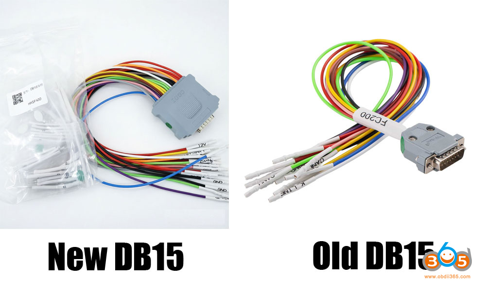
As titled, what is the difference between the new DB15 adapter and old DB15 harness for CG FC200 programmer?
Function:
The function of the new and old adapters is identical.
Both are used for reading and writing ECUs.
Both are equipped with BDCEF-type pins.

Appearance
Material: The material is the same for both versions.
Interface:
Old DB15:
- Red 12V
- Black GND
- Green CAN H
- Yellow CAN L
- White K-line
- Brown GPT-0 5V
- Purple GPT-1 5V
- Pink GPT-2 3.3V
- Blue GPT-3 3.3V
New DB15:
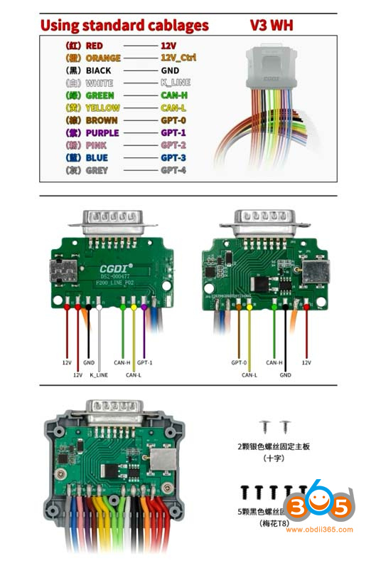
- Red 12V
- Orange 12 Ctrl
- Black GND
- Green CAN H
- Yellow CAN L
- White K-line
- Brown GPT-0 5V
- Purple GPT-1 5V
- Pink GPT-2 3.3V
- Blue GPT-3 3.3V
- Gray GPT-4 3.3V
The wires of the new db15 adapter interface are arranged in a row, while the old adapter interface is aggregated.

Additional Power Port:
The new harness has a DC12 power interface on the side, which can be connected to a 12V power supply (added automatic ignition line control for bench mode); the old adapter does not have this.

Wiring Changes
The new harness adds 2 wires to the original wires of the old version: an orange 12V control wire and a gray GPT-4 3.3V wire.
| Wire Color | Purpose |
|---|---|
| Orange | 12V power |
| Gray | GPT-4 (3.3V) |
Additionally, the new model also has an empty pin position for future expansion.


Orange Wire (12V Ctrl)
Example: When reading a Toyota 37840 encrypted airbag ECU, the old harness required physical disconnection and reconnection of wires during the read/write process.
With the new adapter, this repeated plugging and unplugging is no longer necessary.
Key Difference 1: 12V Power Supply Port
Under normal conditions, the FC200 does not need power from this auxiliary port.
However, if the FC200’s built-in 12V supply current is too low, some ECUs (e.g., MED, EDC types) may fail to wake up.
In such cases, you can supplement power through this external 12V port.
Important: After the launch of the new DB15 harness, subsequent software versions will only support the new harness and no longer support the old one.
Key Difference 2: Voltage Changes on GPT Lines
- The voltage of the original GPT-0 and GPT-2 on the old harness was 5V.
- The new harness changes this to GPT-2 and GPT-3, with a voltage of 3.3V.
- The brown GPT-0 is replaced by the blue GPT-3, and the purple GPT-1 is replaced by the pink GPT-2.
| Old Harness | New Harness |
|---|---|
| GPT-0 (Brown) – 5V | Replaced by GPT-3 (Blue) – 3.3V |
| GPT-2 – 5V | Changed to GPT-2 – 3.3V |
| GPT-1 (Purple) – 5V | Replaced by GPT-2 (Pink) – 3.3V |
| GPT-4 (Gray) – 3.3V (new addition) |
Critical: When wiring, you must follow the new wiring diagram for correct connections.

Key Difference 3: ST10 Series ECUs – No External Resistor Needed
No external resistor is required for voltage division. The original harness required a 1k ohm resistor; otherwise, it would fail to read or produce garbled data.
For example, SIM43, SIM2K-51.4, etc.
New harness: The resistor is no longer required. Simply connect to GPT-3 instead.
For instance, with this wiring diagram, you previously had to connect a 1k ohm resistor, but now you only need to connect GPT-3.

Finally, the upcoming BMW B48, B58, and diesel MD1CS089 encrypted ECU unlocking functions that are about to be released for the FC200 will also require the new DB15 adapter.
FYI: FC200 new DB15 cable pinout