Long story short, I’ve found out that Tactrix has RS232 input which can be used very easily to add any amount of external sensor, eg: oil pressure, fuel pressure, O2 sensor, Knock sensor, WMI flow sensor, etc.
This won’t be a very detailed how to but you should be able to get the idea.
You’ll need:
– Tactrix Open Port 2.0
– Sensors with a 5v output
– A 2.5mm Stereo Jack
– A device to output RS232. I use an Arduino+MAX3232 but you could technically use anything that is able to produce an RS232 signal/stream that respect the OpenPort protocol. Technically something like this could work but I haven’t properly read the documentation nor do I own the product.
How it works – High level
You’ll connect your sensors to an a device than can receive their 5v analog input and transform it an RS232 data stream which will be sent to through a 2.5mm Stereo Jack connected to the OpenPort jack input and add a bit of configuration and that’s it.
Sensors > 5v analog > RS232 conversion > 2.5mm Stereo Jack > Tactrix > Happiness
How it works – Low level
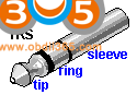
– Make cable with a 2.5mm Stereo Jack. OpenPort pin out for reference
Sleeve = Ground
Ring = RS232 input
– Connect your sensors to an analog/RS232 converter. I used an Arduino so here’s my recipe.
— Connect your sensors to Arduino analog inputs.
— Connect a MAX3232 to your Arduino.
—- MAX3232 TX > Arduino TX (pin 6 in my case, more on that later)
—- MAX3232 GND > Arduino GND
—- MAX3232 VCC > Arduino 5V
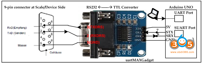
– Connect your 2.5mm Stereo Jack to MAX3232
— Jack ground > MAX3232 GND
— Jack ring > MAX3232 TXDRS
An image will be better illustrate this (note they’re using PIN 7 for tx):
– Connect your 2.5mm Stereo Jack to Tactrix OpenPort stereo jack input.
– Give your Arduino some juice, I’ve used my laptop so far but you can source probably source voltage somewhere in the cabin.
Use this Arduino sketch to get started.
#include <SoftwareSerial.h>
SoftwareSerial tactrix(5, 6); // Arduino RX, Arduino TX

int sensorValueA0 = 0;
int sensorValueA1 = 0;
float sensorVoltageA0 = 0;
float sensorVoltageA1 = 0;

void setup() {
  Serial.begin(9600);
  tactrix.begin(9600);
}

void loop() {
  sensorValueA0   = analogRead(A0);
  sensorVoltageA0 = (sensorValueA0*5.0)/1024.0;
  float afr = (sensorVoltageA0*3)+7.35.7;

  tactrix.print( sensorVoltageA0 );
  tactrix.print(';');
  tactrix.print( afr );
  tactrix.println();

  Serial.print( sensorVoltageA0 );
  Serial.print(',');
  Serial.print( afr );
  Serial.println();
}
The only thing you really need to understand is that we define a secondary TX pin which is set to pin 6 and whenever we use tactrix.print() it sends data over pin 6 to the MAX3232 and then to the Tactrix OpenPort.
The only piece of the puzzle missing is logcfg.txt config.
;----------------aem----------------
; the "ascii" channel type can listen on any protocol for incoming numeric text
; the default protocolid is 9, which corresponds to the 3/32" jack receive-only serial port
; the default baud rate and setting are 9600,N,8,1. all of these can be changed for other scenarios

; the ascii channel considers anything other than the characters {'0'-'9','+','-','.','E','e'} to be a
; delimiter between different numbers. furthermore, the carriage return and line feed characters are
; considered to mark the beginning of a new row of data. you can sample data from a particular column of
; numbers by choosing a paramid starting at 1 which indicates the column number

; in the case of the AEM UEGO, there is simply one column of data, and it is already scaled appropriately

type=ascii

paramname = AFR
paramid = 1
Long story short, send sensor data separated by ; and end each row with a line break.
eg:
sensor1_V;sensor2_V; (end a line break, that’s what the tactrix.println(); does).
paramid1 = first column
paramid2 = second column
eg:
AFR;FuelPressure;
type=ascii

paramname = AFR
paramid = 1

paramname = FuelPressure
paramid = 2
This kind of stuff can be hard to explain in word but hopefully this make sense.
Chuck
Edit: Forgot to mention but since I use an Arduino I can all sort of funky stuff like output to custom gauge or with a CAN Shield broadcast to a PID which I intend to do with a WMI flow sensor to control map blending in RomDrop.