Question:
How to read and write JCB Delphi DCM3.3 ECU? I have MagPro2 x17 master; Flex Master; Ktag 2.23 ; Kess 2.47 ; No clue about it. Read/Write is it ok? Obd? Bench? Boot?
Solution:
Kess V2: Not read it.
Flex: no protocol for this ecu.
Ktag:
genuine tool is fine, ktag clone need luck. Clone Ktag is not a good choice for DCM3.3. There are available 3 different versions of that ecu. The clone tool does not work with all. Need to use original tool.
Review:
When i try to read, then ktag EU Clone 7.020 ksuite get error “Hardware configuration not supported: send the LOG files to the software provider”
I have checked 10x connections, all ok and power supply is 13.5v. and ecu waking up when start connecting.
Foxflash: read/write via bench or Jtag
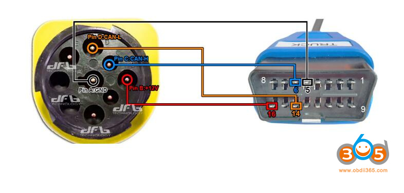
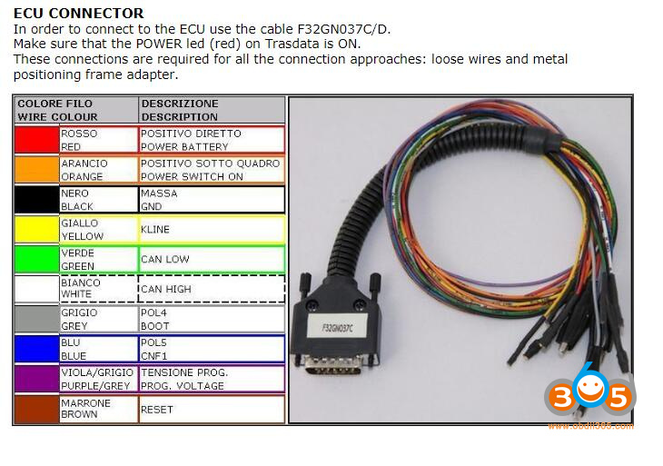
JCB – Round plug 9 pin
To connect use:
– Multifunction cable
– Connectors female-male
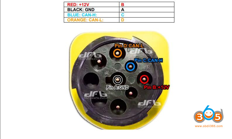
Alternatively make the following connections with:
– OBD cable
– Connectors female-female / crocodile clips
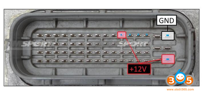
DELPHI DCM3.3+ – JCB [Diesel] Bench Pinout
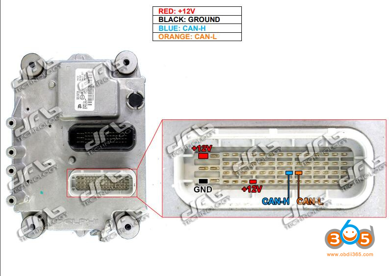
If failed to read it on bench, try jtag mode.
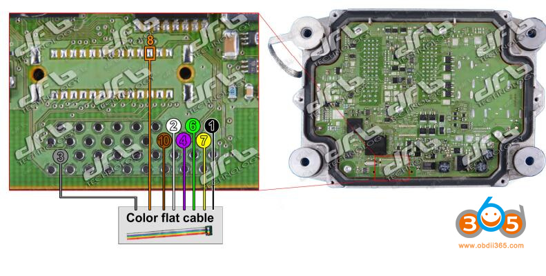
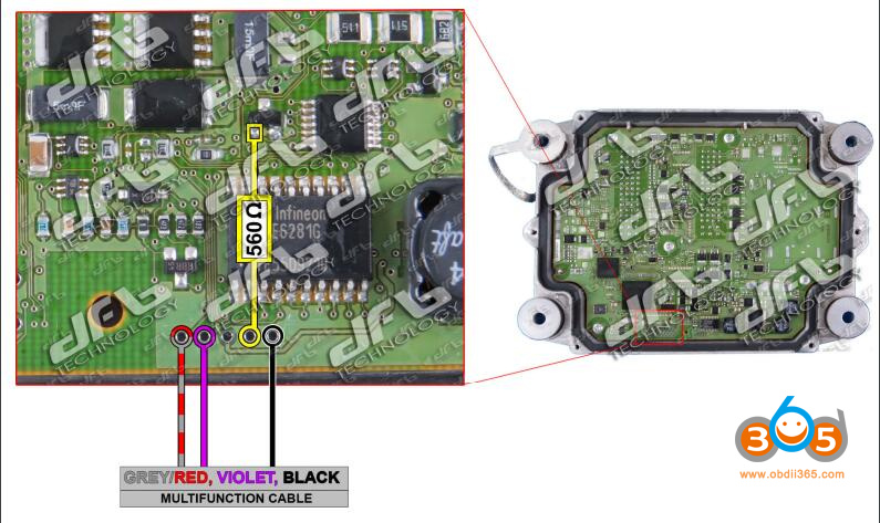
DELPHI DCM3.3+ – JCB [Diesel] JTAG BOOT
Kit to use:
– Multifunction cable
– Flat cable
– 1 resistore 560 Ω
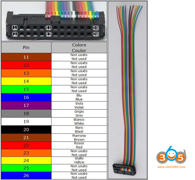
Connect multifunction cable as follows:
To READ the ECU solder the rainbow flat cable.
Use the following driver:
→ BDM / JTAG MODE
→ JTAG RENESAS
→ AUD SH xxxxx
ATTENTION: There are some versions of ECUs that have the JTAG AUD port locked and you cannot read the ECU.
To WRITE the ECU connect the violet, the bicolor grey/red, a black wire of the multifunction cable and also a resistore 560Ω.
Use the following driver:
→ TOOL BOOT
→ RENESAS
→ SH xxxxx BOOT MODE
Genuine New Trasdata: will read and write via Jtag
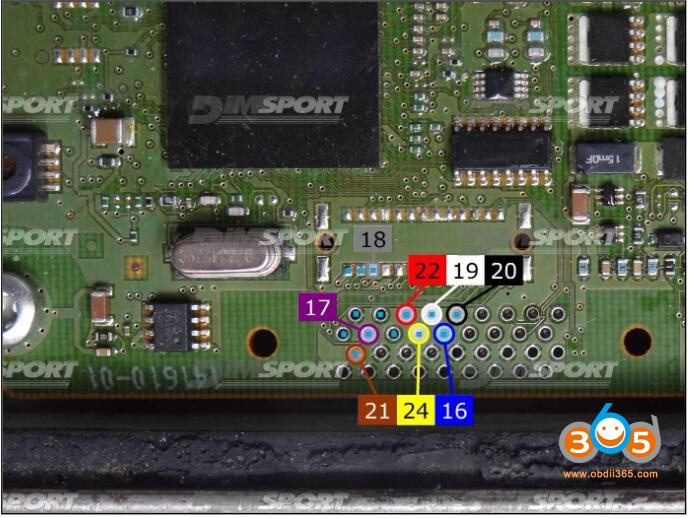
DELPHI DCM3.3 JTAG JCB pinout:
plugin 1050
For the reading & writing procedures use the FLAT cable F34NTF53
Connect the wires on the pads avoiding any short circuits.
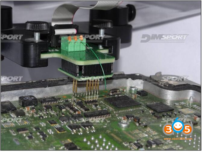
METAL POSITIONING FRAME CONNECTION
For the metal positioning frame connection are required the F34DM036 +F34DM037 adapters,
JTAG pads for the communication are placed below the microprocessor.
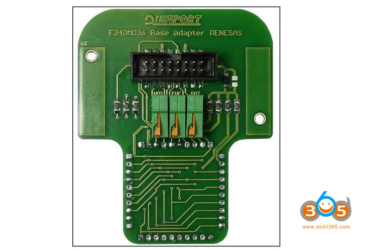
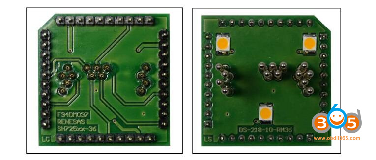
Set up the base adapter F32DM036 with the F34DM037 adapter as displayed in the following picture.
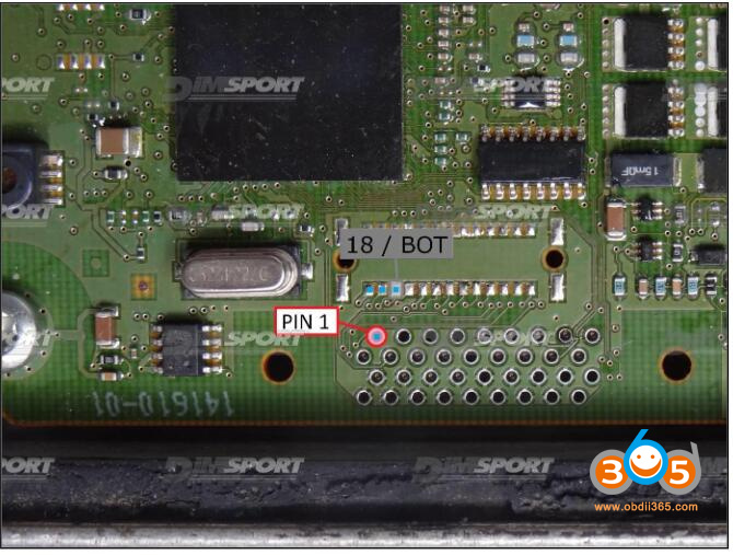
Verify the PIN 1 location and connect the pin 18/BOT to the corresponding clamp on the base adapter F34DM036 as in displayed in the following picture.
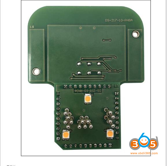
Place F34DM036+F34DM037 adapters as displayed in the following picture.
NOTE:
This ECU is expensive. Opening ECU is little tricky. Be careful.