Here comes the Launch X431 Tesla adapter function list and wiring diagrams. Hope it helps.
Content:
- Launch X431 Tesla 12+20 connector
- Launch X431 Tesla airbag reset adapter
- Launch X431 Tesla 3 battery test cable
- Launch X431 Tesla LAN adapter
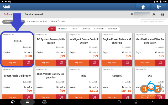
To use these adapters you should have Tesla software activated on your Launch X431 scanners.
The software for “TESLA” is compatible with LAUNCH X431 PAD VII, PAD V, PAD II, X431 V 8inch, X431 V+, X431 Pro5, Pros V1.0, Pros V5.0, Pro3s+, X431 Throttle etc)
Check how to purchase Tesla software and the supported vehicle list here
https://www.obdii365.com/wholesale/launch-x431-tesla-diagnostic-software.html
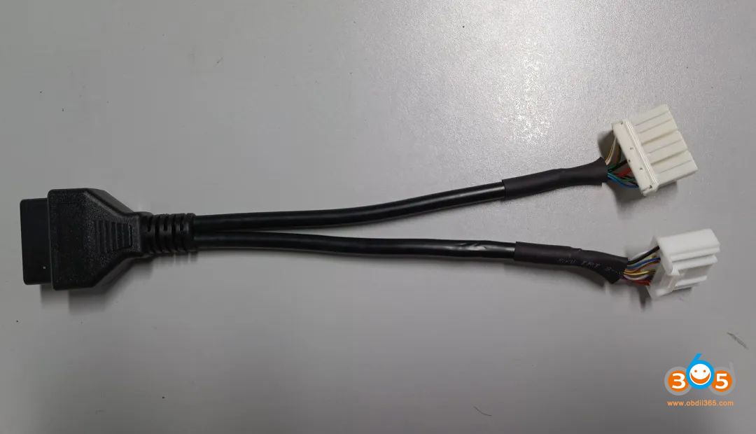
1. Launch Tesla 12+20 Connector
The Tesla 12+20 adapter is included in the Launch X431 EV kit
It can be purchased alone as well.
The connector can be used on Model S and Model X vehicles.
Function:
Basic Function including ECU Information, Live Data, Read/ Erase Codes, as well as Special Functions including BMS Reset Alert, BMS Clear Contactor Stress Index, EPB Service Mode, Brake Bleed etc for Model X and Model S.
The specific wiring diagram is shown in Figure 2. The first part is the Tesla 12+20 connector (12PIN) wiring diagram, which is applicable to S (X) models produced before September 2015 (including September). The second part is the Tesla 12+20 connector (20PIN) wiring diagram, which is applicable to S (X) models produced after September 2015.
Check vehicle and function coverage here http://qcar.x431.com/qcar/#/
Wiring diagram:
1.12 PIN connector: (located below the central control screen) for diagnostics of pre-2015/Sept Model S and Model X
2. 20PIN connector: (located below the central control screen) for diagnostics of post-2015/Sept Model S and Model X
* Need to supply 12V external power supply to the Smartlink VCI connector.
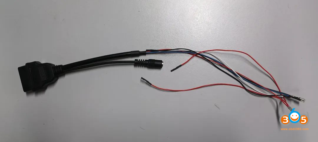
The picture of Tesla airbag repair special connector is shown below
The Tesla airbag repair dedicated connector is mainly used to reset the airbag crash data.
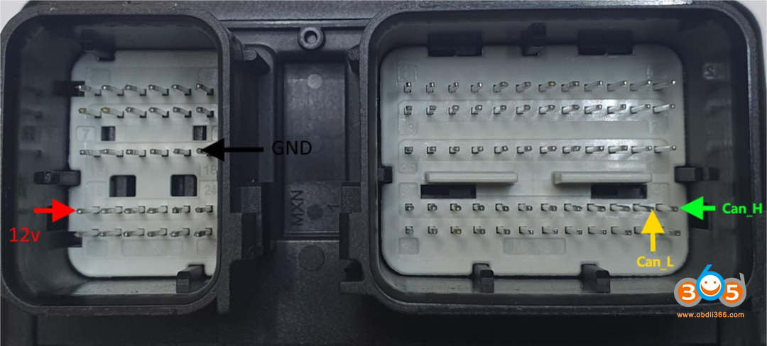
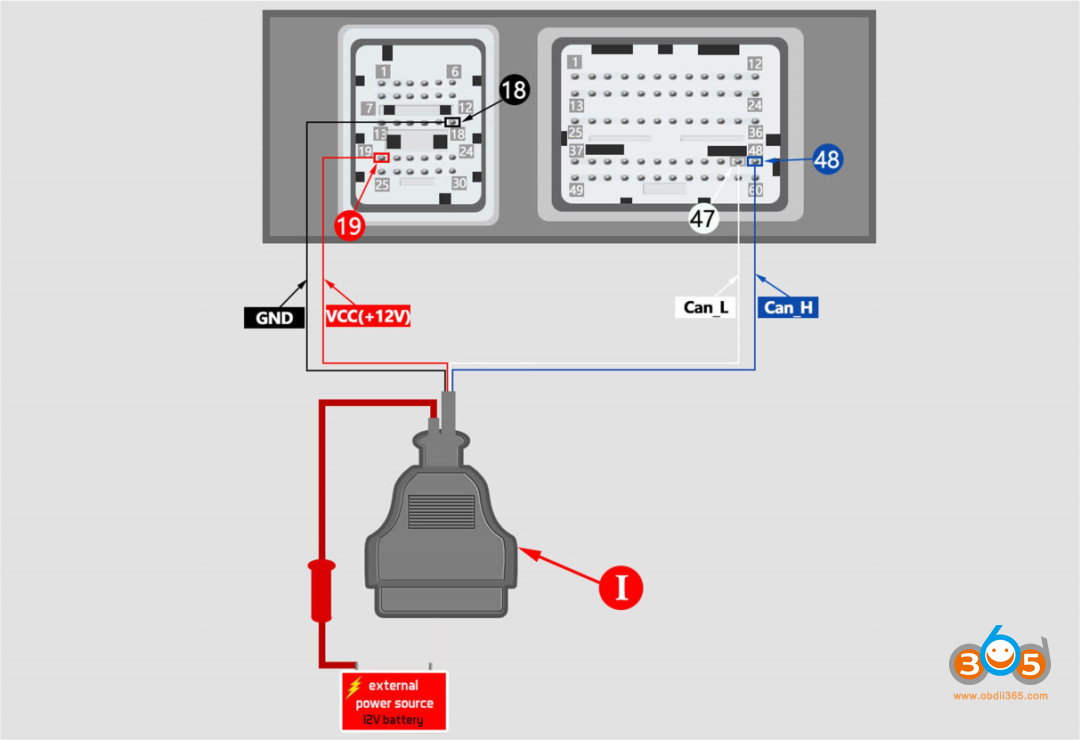
1). Model X airbag control module pinout
The flying wires and pins of the airbag control unit interface for Model X are shown below
+12V: 12V Power
GND: Ground
CAN_H: CAN High
CAN_L: CAN LOW
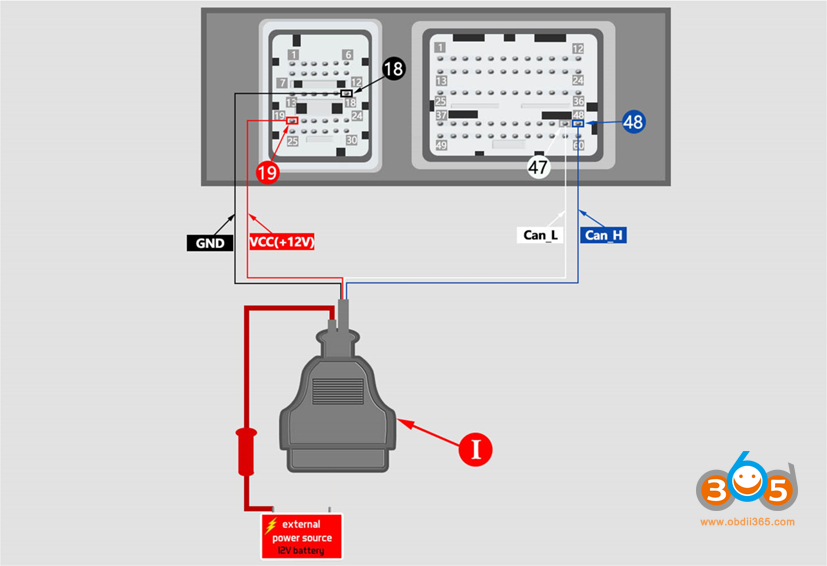
Model X Tesla airbag connector connection diagram:
The wiring diagram of the Model X Tesla airbag repair dedicated connector is shown below
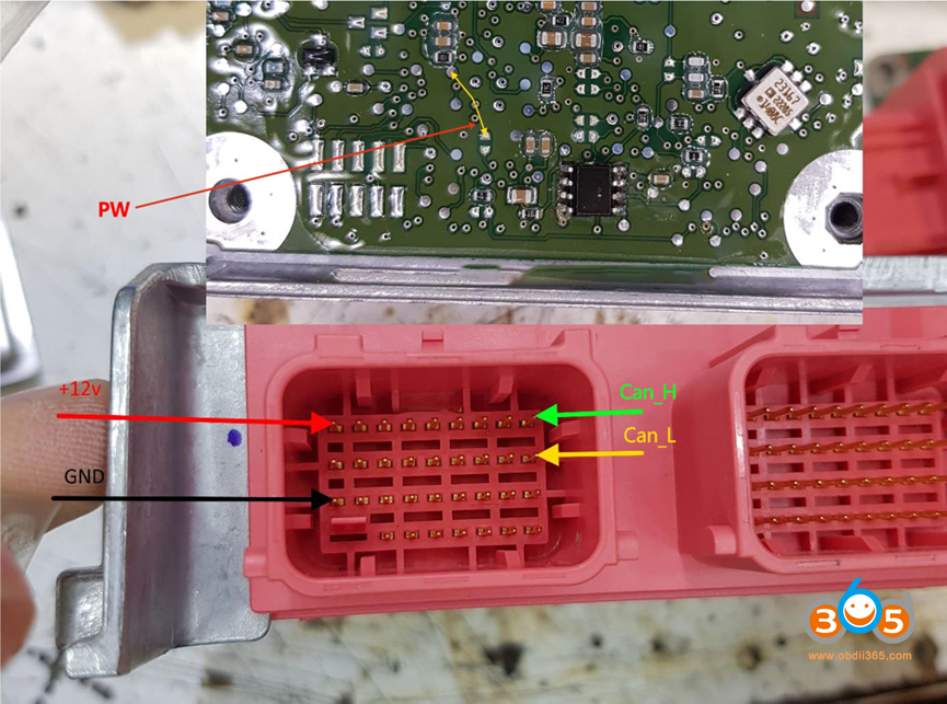
2). Model S airbag control module pinout
The flying wires and pin descriptions of the airbag control unit interface for Model S models are shown below
PW: Jump wire, short the two positions to enable it to write EEPROM;
+12V: 12V Power
GND: Ground
CAN_H: CAN High
CAN_L: CAN LOW
Model S Tesla airbag connector connection diagram:
The wiring diagram of the Model S Tesla airbag repair dedicated connector is shown below
Example:
How to Reset Tesla Model S Airbag Crash Data with Launch X431?
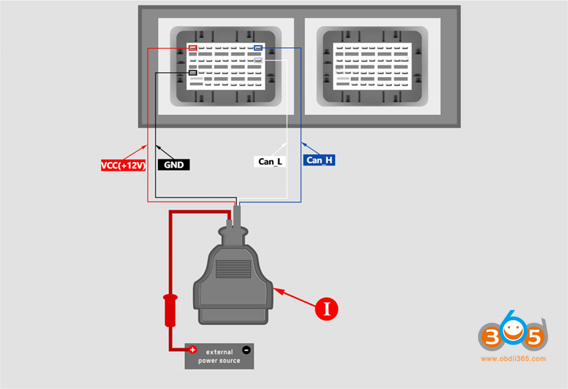
3). Model 3 airbag control module pinout
The flying wires and pin descriptions of the airbag control unit interface for Model 3 are shown below
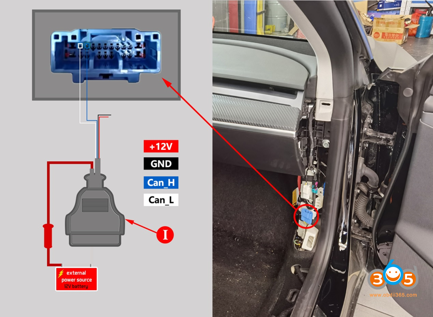
Model 3 Tesla airbag connector connection diagram:
The wiring diagram of the Model 3 Tesla airbag repair dedicated connector is shown below
4). Model 3/Y Airbag Unlock Wiring Diagram
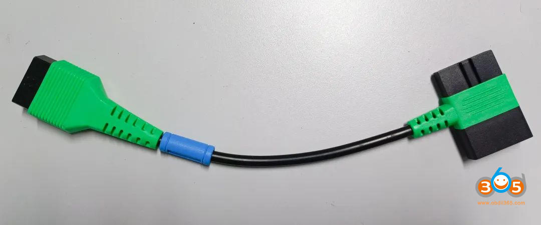
3. Tesla 3 Battery Test Cable 152, RoHS
The cable is included in the Launch X431 EV kit
The picture of the 124 Tesla 3 battery pack test line is shown below
Used for Tesla battery pack low-voltage communication interface and battery pack testing.
Tesla 3 battery pack test line 152 models, RoHS
Tesla 3 battery pack test line 152 models, RoHS image as shown
This test line is used for testing the data flow of the three electric systems of Model 3 and Model Y models, as well as for testing the battery pack.
The EV kit is compatible with PAD VII, X431 PAD V, Pro5, PAD VII Elite, PRO3 V+ 5.0, PRO3(PRO3S+ V5.0), PRO3 ACE, PRO3 APEX etc diagnostic scanners.
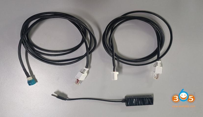
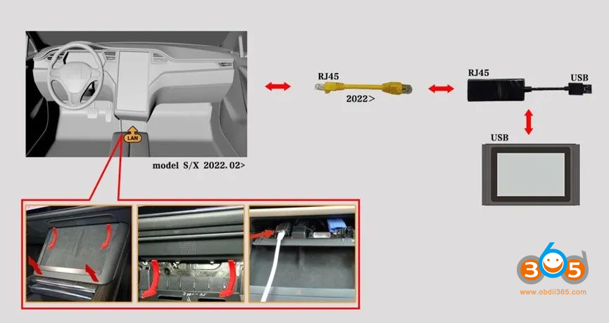
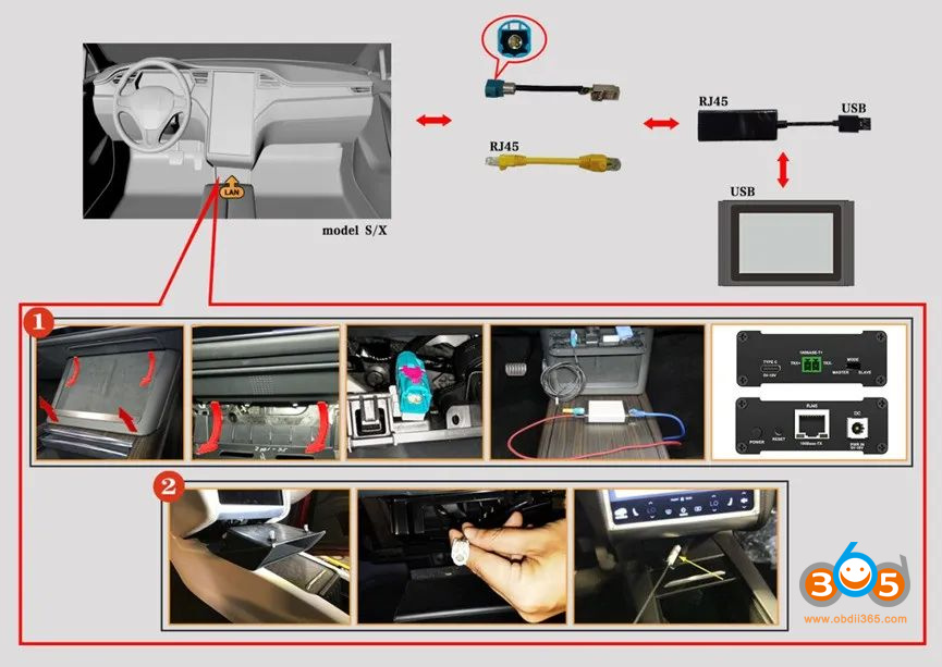
4. X-431 New Energy LAN Network Interface Diagnostic Connector Configuration Connector
Launch X431 New Energy LAN network port diagnostic connector
Used in local area network (LAN) function to enable Tesla Service Mode, currently supported products: X-431 PAD III, PAD V, PAD VII series, EV MAX, X431 PRO 3S+ V3.0/V5.0 diagnostic equipment, Simplified Chinese, Traditional Chinese, Japanese, Korean, Arabic and Russian software.
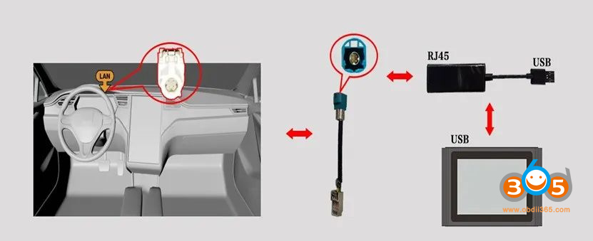
The specific equipment wiring diagram is shown below:
Wiring diagrams
1). 2018 onwards Model 3/Model Y
2). Model S/X from 2012 to 2018
3). 2022 onwards Model S/Model X
4). 2012-2018 Model S/Model X
4). 2014-2018 Model S/X Tegra chip MCU
Check: How to Enable Tesla Service Mode with Launch X431 & LAN Cables


