0.) Order 2 of this socket [Part Number 2057-PLCC-52-AT-NO about $6.50 US from digikey (#2 is in case you screw up ..you know you do).
1.) Chop the socket from the end of the cable with scissors. keep as much cable length as you can
2.) Salvage the white shrink wrap intact if you can. Its useful later. Stretch it as little as possible.
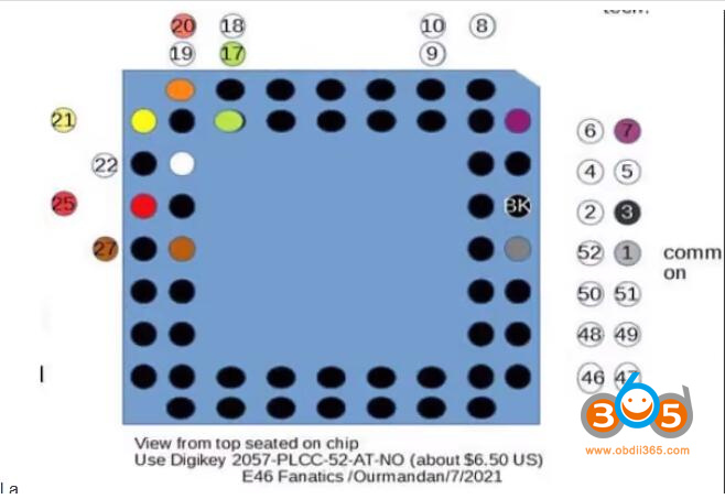
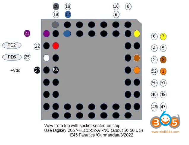
3.) Compare the 2 known cable pattern photos below & pick the matching socket pin-out.
4,) Carefully separate the wires for about 1 inch
Either blue or green will appear on your solder map. Don’t strip the un-used B or G, we’ll need that as a strain relief.
trim down 50% length from the unused pins. I folded mine over being careful not to touch. It gets them out of the way of the wires and stopper
Strip all other wires 1/4 in & twist the wires in each then tin.
>>> Don’t forget to thread the white shrink <<<<<
Solder the wires in place. I used needle nose to make a ‘U” around each pin. I alternated pins across the socket to keep the wires from bending to the breaking point.
Once about half the wires are soldered, use a little “Shoe goo” from Walmart or similar to anchor the unused “Strain relief” wire (blue for me) to the middle of the socket. adjust its length to relieve tension on the wires, solder the remainder.
Almost done! You can shrink the white plastic back down on the socket .. but don’t melt the socket! a tiny amount (use toothpick) of Shoe-goo is a fine alternative.
finally cut your white shrink a bit under 1/8th all the way around the socket. Use a new razor blade straight-on to keep it consistent. the shrink cuts easily. So do your fingies.
Now we need to add a little handle, because you still have to jockey the socket in place and we need to relieve strain on the wires too.
If you live in the USA go to Ace Hardware , go to the parts bins and select the 50 cent black rubber cork. That’s the one that fits well. Use a little shoe goo from Walmart
or silicone rubber to secure the cork reasonable deep into the shrink. If you don’t have Ace where you live you are on your own.
If you aren’t used to cable building, seek out original post with more detailed instructions or contact me; if I’ve time I’ll make a cable for you .. you’ll pay for parts (about 10.00)
(your AK90+ will work every time).
Finally Mark the flat corner on the shrink with a sharpy. Always line it up with the flat corner of the chip. When you insert the socket it should be more of a “slide in from a side” then finesse the other sides down a little. The socket I specified has much springier pins so if you are gentle it will work almost every time.
Dont forget to remove any red coating on the processor pins. You can use alcohol, acetone on a qtip, or a thin nail file if you must .. but wipe it with a q-tip if you do that.
OK now you’ve got the con .. over and out.
Read this addendum
A recent cable issue was discovered by the fanatic known as “sideways”.
A variant of the OEM AK90+ cable wire color key has been found. For those who have the variant, my “how-to” pin out map would be incorrect.
Before you make the changes you must chose the soldering schema matching YOUR AK90+ cable.
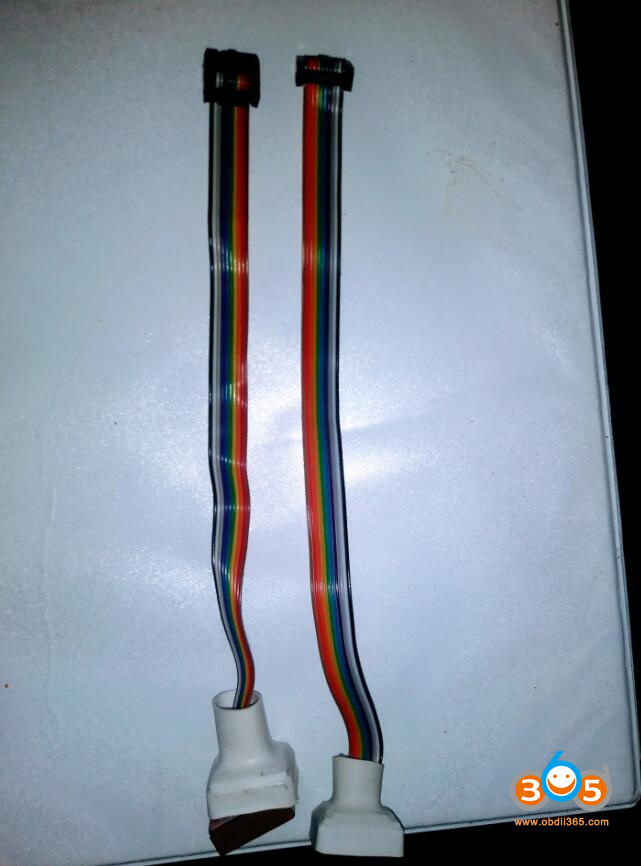
Here is a side by side of both possible cables. Plug the connector into the AK90, then determine if the left-most wire is brown or black. Then step down and pick the schema that matches your cable. IMPORTANT: my soldering schemas are shown as if the socket is sitting on top of the EWS Chip.
If you’ll be building a cable, scan the photos & drawings, then skip t the bottom for a few pointers .

Use this solder plan if your cable matches the photo on the left. (Left wire of the cable is Black (when plugged into the AK90)
Use this solder plan if your cable matches the photo on the right. (Left wire of ribbon is Brown when plugged into the AK90) .
Addendum:
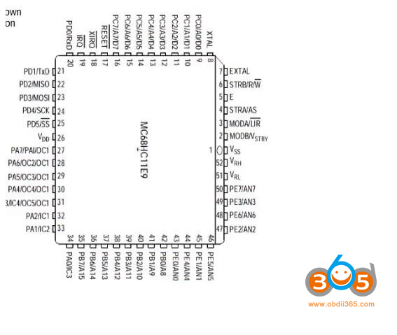
The processor pin-out below is only for those who are curious & want to know the purpose of each processor pins connected to the cable. You can make a working cable without looking at it.


