PCM–FLASH module 53 is for qualified users only and requires access to the ECU pcb and in some cases the soldering of additional components. The work is performed in bench mode (BUT ECU disassembling is required).
Here is the PCM Module 53 – Infineon Tricore BSL operation guide
NOTE: CAN Bootstrap Loader (BSL) is a mode where is the ecu is forced into boot mode by accessing the processor by manipulating certain parts of the PCB, usually vias or pads.
The module supports many ECU’s with the TC1724, TC1728, TC1736, TC1738, TC1762, TC1766, TC1767, TC1782, TC1792, TC1793, TC1796, TC1797 and TC1798 microcontrollers of Bosch, Siemens / Continental and Delphi ECUs.
The password can be read from SIM2K-24x, Ford EMS22XX, Ford SID20X, Bosch, Bosch GPT ECUs.
The opens possibilities to MANY ecus not supported by other modules.
Compatibility
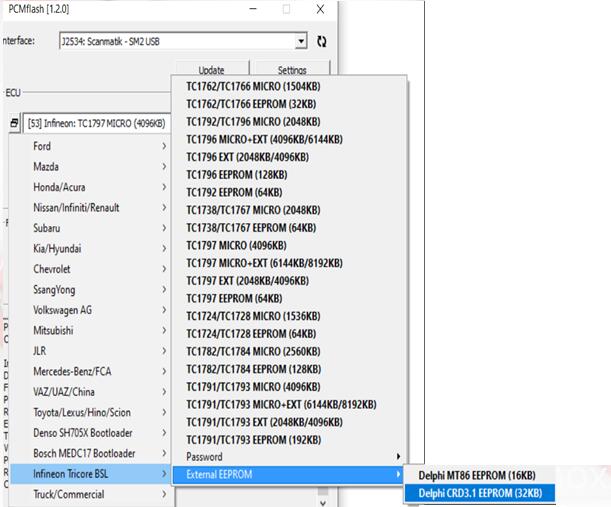
TC1762/TC1766 MICRO (1504KB)
TC1762/TC1766 EEPROM (32KB)
TC1792/TC1796 MICRO (2048KB)
TC1796 MICRO+EXT (4096KB/6144KB)
TC1796 EXT (2048KB/4096KB)
TC1792 EEPROM (64KB)
TC1796 EEPROM (128KB)
TC1736 MICRO (1024KB)
TC1736 EEPROM (32KB)
TC1738/TC1767 MICRO (2048KB)
TC1738/TC1767 EEPROM (64KB)
TC1797 MICRO (4096KB)
TC1797 EEPROM (64KB)
TC1797 MICRO+EXT (6144KB/8192KB)
TC1797 EXT (2048KB/4096KB)
TC1724/TC1728 MICRO (1536KB)
TC1724/TC1728 EEPROM (64KB)
TC1782/TC1784 MICRO (2560KB)
TC1782/TC1784 EEPROM (128KB)
TC1791/TC1793 MICRO (4096KB)
TC1791/TC1793 EEPROM (192KB)
TC1791/TC1793 MICRO+EXT (6144KB/8192KB)
TC1791/TC1793 EXT (2048KB/4096KB)
Delphi MT86 EEPROM (16KB)
Delphi CRD3.1 EEPROM (32KB)
Tested ECUs
Bosch
VAG MED17.1 TC1796
VAG MED17.1.1 TC1796
VAG MED17.1.6 TC1797
Ford MED17.2 TC1767 TPROT7
Ford MED17.2 TC1767 GPT
BMW MEVD17.2.4 TC1797 GPT
BMW MEVD17.2.9 TC1797 GPT
VAG MED17.5 TC1766
VAG MED17.5.5 TC1766
VAG MED17.5.5 TC1766 GPT
VAG MED17.5.5 TC1767 GPT
VAG MED17.5.21 TC1782 GPT
VAG ME17.5.26 TC1724 GPT
MB MED17.7.1 TC1797 TPROT7
MB MED17.7.2 TC1797 GPT
PSA MED17.4.4
China ME17.8.8 TC1728
K/H MEDG17.9.8 TC1767
VAZ ME17.9.7 TC1762
K/H ME17.9.11 TC1762
K/H ME17.9.13 TC1762
UAZ ME17.9.71 TC1724
BMW EDC17CP02 TC1766 TPROT3
PSA EDC17C10 TC1797 TPROT7
PSA EDC17C60
MB EDC17CP10 TC1796+EXT
K/H EDC17CP14 TC1796 TPROT3
K/H EDC17CP14 TC1796 TPROT11
VAG EDC17CP14 TC1796
VAG EDC17CP14 TC1796+EXT
VAG EDC17CP14 TC1796+EXT GPT
VAG EDC17CP20 TC1796
BMW EDC17C41 TC1797 GPT
VAG EDC17CP44 TC1797 TPROT8+
VAG EDC17C46 TC1767 TPROT8+
VAG EDC17C46 TC1767 GPT
MB EDC17CP46 TC1797 GPT
Volvo EDC17CP48 TC1797 GPT
Iveco EDC17C49 TC1797
Iveco EDC17CP52 TC1797
K/H EDC17C53 TC1767 TPROT8+
VAG EDC17C54 TC1797 TPROT8+
BAW EDC17CV54 TC1767
BMW EDC17C56 TC1797 GPT
K/H EDC17C57 TC1793F TPROT8+
MB EDC17CP57 TC1793 GPT
GM EDC17C59 TC1767 GPT
VAG EDC17C64 TC1797 GPT
VAG EDC17C74 TC1793 GPT
Siemens / Continental
K/H SIM2K-241 TC1767
Ford SID208/SID209 TC1797
Ford EMS2204/EMS2211 TC1738
JLR SID208
Delphi
GM MT-60 TC1766
China MT-80 TC1762
GM MT-80 TC1762
K/H MT-86 TC1766
MB CRD 3.10 TC1797
CRD3/CRD3P
Working Example.
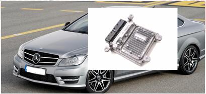
For our example we are going to Read and write both Flash memory and EEPROM from a Delphi CRD3.10 in this case, the ecu is from a 2012 Mercedes C250 blue efficiency model, a car not on our current module list.
With a little research we can find
- ECM type and specifications
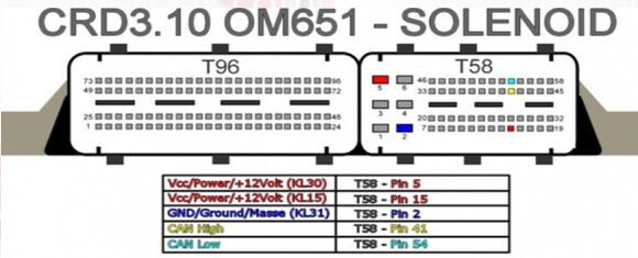
- ECM pinouts
- boot loader connections for pcb
Processor type TC1797
Password: Not implemented
Eeprom external
Step 1
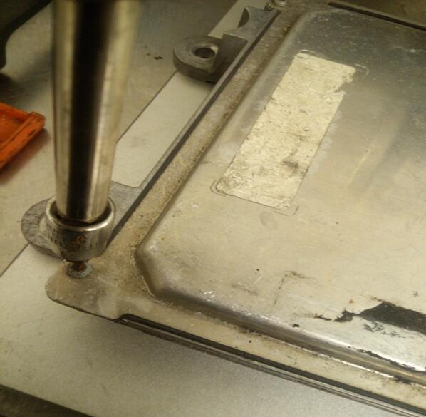
We need to dismantle the ECU in order to access the PCB to enable us to place the ecu in boot mode so that we can read/write.
First we remove the screws from the ecu case.
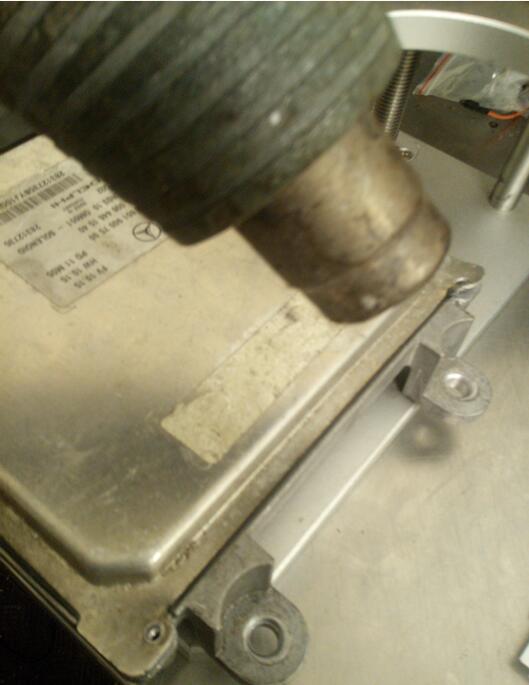
Next, using a heat gun, we gently heat the edges of the ECU lid to help loosen the bonding material, whilst gently prying the lid. Care must be taken not to use excessive heat or force!!
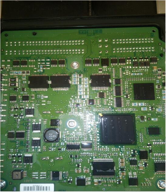
After removing the Lid we now have access to the ECU’s pcb.
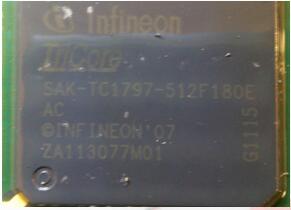
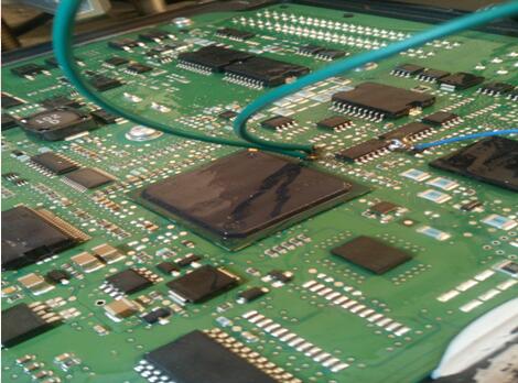
Closer inspection of the processor shows it to be a tricore 1797
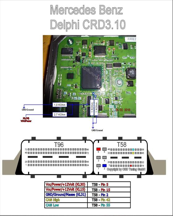
Now we must prepare the PCB for boot mode. Below are just some of the Schematics available via online resources on how to place this ecu into BSL or boot mode. Some some will show connections for resistors to be soldered. These type are usually our last resort if we cannot use our boot and cnf cables.
Others may show the Labels L and H
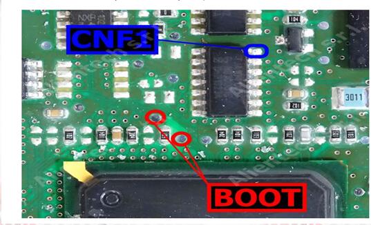
and others BOOT and CNF1
L = Boot H = CNF1 which also relate to the cables on PCM bench wires with crocodile clips.
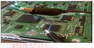
In order to connect to the points shown we can use pen probes (recommended ) or we can solder leads directly to these points that are usually pads, vias or IC pins.
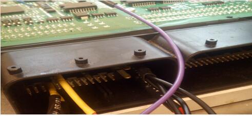
With our PCMtuner interface NOT powered, we can connect or bench cable to the ECU
And connect our BOOT and CNF1 to the appropriate leads or Probe pens on the PCB
Step 2.
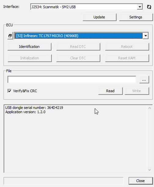
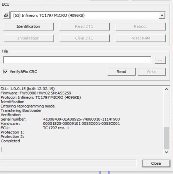
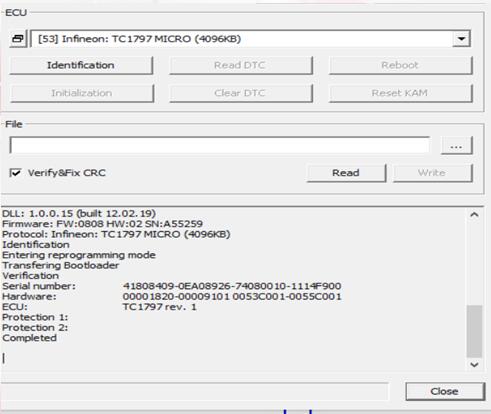
Power on our PCMtuner hardware, open PCMflash, and select module 53 TC1797 Micro (4096kb)
Our Micro is where our flash memory containing maps etc is located.
Next we click on Identification to ensure our connections and selection is correct :
If you cannot ID then please check all connections to PCB, check ECU pinouts, or, in some cases you may have to revert to a diagram that shows boot and cnf connections as resistors rather than a physical connection to your bench cable.
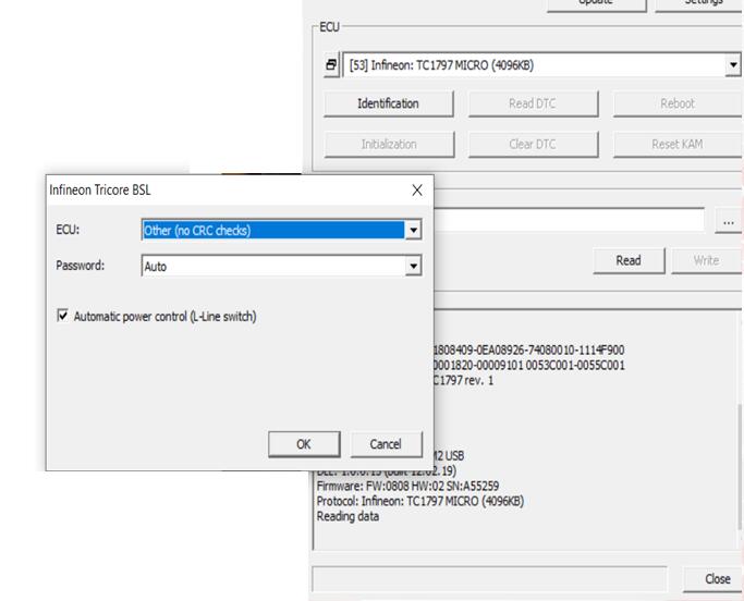
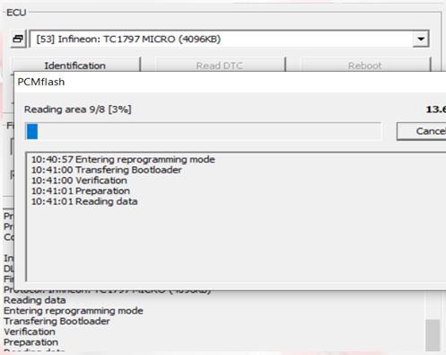
Next we click on Read, We will be asked to select password, in this ECU case we specify that it is not implemented.
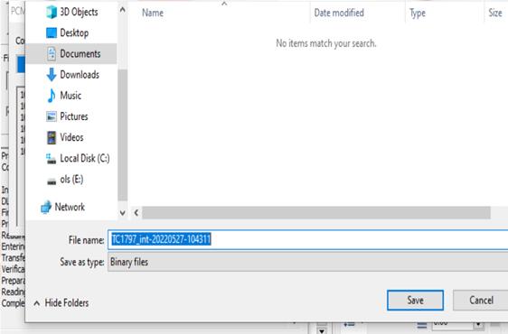
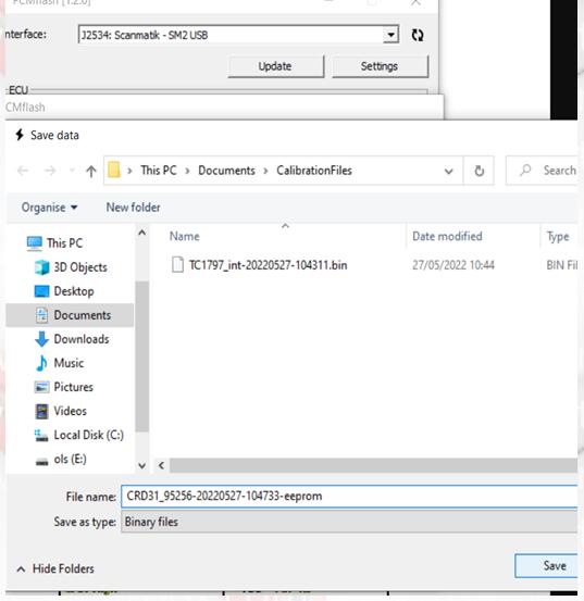
When read is complete we will be asked to save the file
click save…
Now we will read our eeprom.
In the case of this particular ECU its is an external Ic, so we select the option via MODULE 53>>external eeprom>>Delphi CRD3.1 eeprom
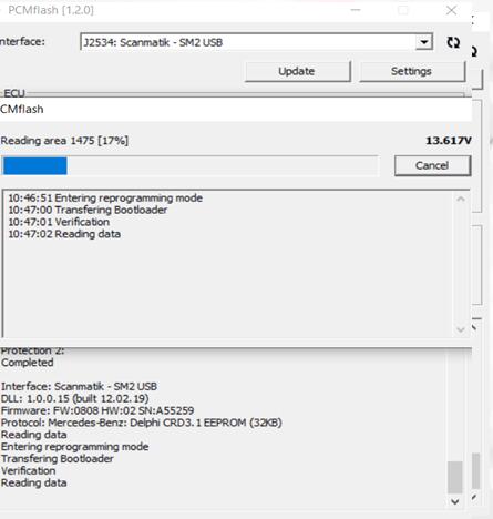
Again, click Identification..then read
and again save on the computer when done
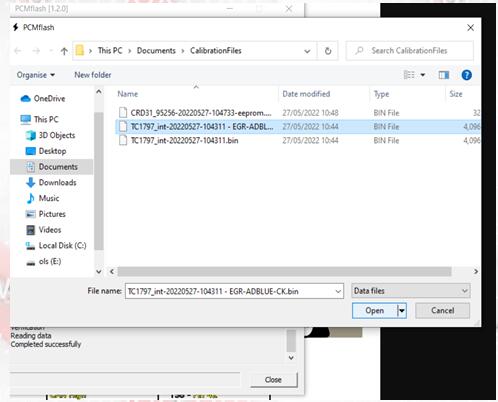
To write a file to flash, we select our micro and click the file selection box
we then choose the file we wish to write…..
we then choose the file we wish to write…..
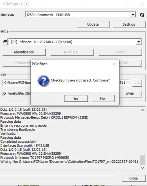
On this Particular ECU we must do our checksum before in our file editor as this automatic checksum
So we click Yes
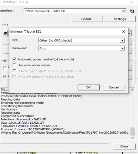
For our ECU we must select ‘other (no crc checks) in the first drop down box.
Password is Auto (as not used on this ecu)
‘use write optimizations’ is unchecked. This means the full flash file is written. If checked, only changes in the file will be written to Flash – We then click OK
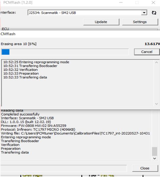
Sit back, have a beer and wait on your latest masterpiece being written to the ECU
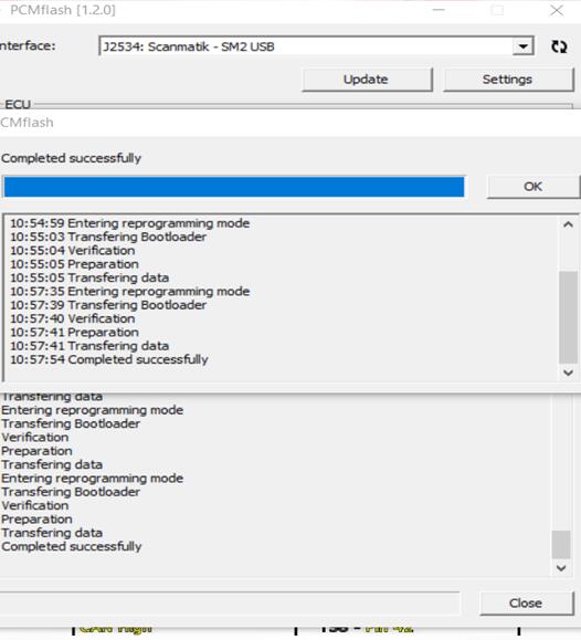
If all goes to plan….Successful write!!!
If using Scanmatik 2 pro, here is the pinout
ption 1. Direct connection to Scanmatik 2 OBD connector:
OBD1-GPT1
OBD2-GPT2
OBD4, 5 – ground
OBD6-CAN-H
OBD14-CAN-L
OBD16 – +12V
It is MANDATORY to install a 120 ohm resistor between CAN-H and CAN-L!
Option 2. Direct connection to DB25 Scanmatik 2:
DB25-23 – GPT1
DB25-4 – GPT2
DB25-20, 21 – mass
DB25-8 – CAN-H
DB25-9 – CAN-L
DB25-1, 2- + 12V
It is MANDATORY to install a 120 ohm resistor between CAN-H and CAN-L!
Foxflash/KT200 can do CRD3 on bench if you have it.


